The concept of " information network” (in contrast to the concept of “telecommunication network”) is more capacious and reflects the whole variety of information processes performed in the network when end systems interact through a telecommunication network. The telecommunications network, thus, as part of the information network performs the functions transport system, through which the movement of user and service information flows generated by information processes is carried out.
In general, under information network How physical object should be understood a set of geographically dispersed end systems united by a telecommunications network, through which the interaction of application processes activated in end systems and their collective access to network resources is ensured.
All intellectual work in the information network, as we see (see Fig. 3), is performed on the periphery, i.e. in the end systems of the network, and the telecommunications network, although it occupies a central position, is only a connecting component. The information network is essentially intelligent add-on over a telecommunications network through which users(Users) provides mechanisms for processing information, its effective search anywhere in the network and at any time, as well as the possibility of its accumulation and storage.
So, the concept of "information network" in our case indicates a shift in the focus of attention when studying or researching an info-communication network towards information processes that occur in the network when end systems interact through a telecommunications network. The description of this interaction demonstrates the complexity of building a communication architecture in a network (the communication architecture is discussed in detail later in the course of lectures).
Information processes networks can be divided into two groups. The first of these includes application processes(Application Processes). They dominate the network. Application processes are initiated when user programs called applications(Applications). All other processes in the network (determining the formats for presenting information for transmission over the network, establishing data transfer modes, promotion routes, etc.) are auxiliary and are designed to serve application processes. They form a group of so-called interaction processes(Interworking Processes). Application and interaction processes are supported network operating systems(SOS).
Figure 3. Information network
Information network resources are divided into information resources, data processing and storage resources, software and communication resources.
Informational resources represent information and knowledge accumulated in all areas of science, culture and society, as well as products of the entertainment industry. All this is systematized in network databanks with which network users interact. These resources determine the consumer value of the information network and should not only be constantly created and expanded, but also archived and updated in time, and the use of the network should provide the opportunity to receive up-to-date information just when it is needed.
Data processing and storage resources is the performance of the processors and the amount of memory of computers operating on the network, as well as the time during which they are used.
Program resources are network software: server software, workstation software and drivers; application software focused on the use of network capabilities and involved in the provision of services to users; tools: utilities, analyzers, network control tools, as well as programs for related functions. The latter include: issuing invoices, accounting for payment for services, navigation (providing the search for information on the network), servicing network electronic mailboxes, organizing bridges for teleconferencing, converting formats of transmitted information messages, cryptographic protection of information (encoding and encryption), authentication (in particular, electronic signature of documents, certifying their authenticity).
Communication Resources are the resources involved in the transportation and redistribution of information flows in the network. These include the bandwidth of communication lines and equipment of nodal points, as well as the time they are occupied when the user interacts with the network. They are classified according to the type of transmission medium and telecommunication technology used.
All listed resources in the information network are shared, i.e., they can be used simultaneously by several application processes.
The main requirement for an information network is to provide users with efficient access to shared resources. All other requirements - throughput, reliability, survivability, quality of service - determine the quality of this basic requirement.
The concept of " information network” (in contrast to the concept of “telecommunication network”) is more capacious and reflects the whole variety of information processes performed in the network when end systems interact through a telecommunication network. The telecommunications network, thus, as part of the information network performs the functions transport system, through which the movement of user and service information flows generated by information processes is carried out.
In general, under information network How physical object should be understood a set of geographically dispersed end systems united by a telecommunications network, through which the interaction of application processes activated in end systems and their collective access to network resources is ensured.
All intellectual work in the information network, as we see (see Fig. 3), is performed on the periphery, i.e. in the end systems of the network, and the telecommunications network, although it occupies a central position, is only a connecting component. The information network is essentially intelligent add-on over a telecommunications network through which users(Users) provides mechanisms for information processing, effective search for it anywhere on the network and at any time, as well as the possibility of its accumulation and storage.
So, the concept of "information network" in our case indicates a shift in the focus of attention when studying or researching an info-communication network towards information processes that occur in the network when end systems interact through a telecommunications network. The description of this interaction demonstrates the complexity of building a communication architecture in a network (the communication architecture is discussed in detail later in the course of lectures).
Information processes networks can be divided into two groups. The first of these includes application processes (ApplicationProcesses). They dominate the network. Application processes are initiated when user programs called applications(Applications). All other processes in the network (determining the formats for presenting information for transmission over the network, establishing data transfer modes, promotion routes, etc.) are auxiliary and are designed to serve application processes. They form a group of so-called interaction processes (interworking processes). Application and interaction processes are supported network operating systems(SOS).
Figure 3. Information network
Information network end systems
The end systems of an information network can be classified as:
terminal systems(TerminalSystem) - computers of end users of the network;
hosting systems(HostSystem) - computers that host information and software resources of the network;
servers ( Servers ) – computers that can provide network services. For example, managing access to information resources and shared devices, registering users and controlling their access rights to the network, servicing calls, etc. Servers, depending on the capabilities of their operating systems, can operate both in the mode of hosts (information servers) and in the mode of network communication devices;
administrative systems(ManagementSystem) - computers and devices that provide operational management applications for the network and its individual parts.
NOTE. Since computers act as end systems of an information network, it is also called a “computer network”. In this case, the telecommunications network is classified as a "data transmission network" (the previously used classification according to the type of information transmitted).
Information networks are designed to provide users with services related to the exchange of information, its consumption, as well as processing, storage and accumulation. An information consumer who has gained access to an information network becomes its user (User). Both individuals and legal entities (firms, organizations, enterprises) can act as users. In the general case, by an information network we mean a set of geographically dispersed end systems and a telecommunications network that unites them, providing access for application processes of any of these systems to all network resources and their sharing.
The Application Process is a process in a network end system that performs information processing for a particular communication service or application. So, the user, organizing a request for the provision of a particular service, activates in his end system some application process.
The end systems of an information network can be classified as:
terminal systems (Terminal System), providing access to the network and its resources;
working systems (Server, Host System), providing a network service (access control to files, programs, network devices, call handling, etc.);
administrative systems (Management System), implementing the management of the network and its individual parts.
Information network resources are divided into information, resources data processing and storage, software, communication resource s. Information resources are information and knowledge accumulated in all areas of science, culture and society, as well as entertainment industry products. All this is systematized in network databanks with which network users interact. These resources determine the consumer value of the information network and must not only be constantly created and expanded, but also updated in time. Obsolete data should be dumped into archives. Using the network provides the opportunity to receive up-to-date information, and just when it is needed. Data processing and storage resources are the performance of the processors of network computers and the amount of memory of their storage devices, as well as the time during which they are used. Software resources are software involved in the provision of services and applications to users, as well as programs of related functions. The latter include: issuing invoices, accounting for payment for services, navigation (providing information search on the network), maintaining network electronic mailboxes, organizing a bridge for teleconferencing, converting formats of transmitted information messages, cryptographic protection of information (coding and encryption), authentication (electronic signature of documents certifying their authenticity).
Communication resources are resources involved in the transport of information and the redistribution of flows in communication nodes. These include the capacities of communication lines, the switching capabilities of nodes, as well as the time they are occupied when a user interacts with the network. They are classified according to the type of telecommunications networks: public switched telephone network (PSTN) resources, packet-switched data network resources, mobile network resources, terrestrial broadcast network resources, integrated service digital network (ISDN) resources, etc.
All listed information network resources are shared, i.e., they can be used simultaneously by several application processes.
In this case, separability can be both actual and simulated.
The basic component, the core of the information network, is telecommunications network. Let us clarify this concept when considering it within the framework of an information network.
Telecommunication network TN (Telecommunication Network) is a a set of technical means that ensure the transmission and distribution of information flows during the interaction of remote objects.
Both end systems of information networks and separate local and territorial networks can act as remote objects.
It is customary to evaluate telecommunication networks with a number of indicators that generally reflect the possibility and efficiency of transporting information in them. The possibility of transmitting information in a telecommunications network is related to the degree of its operability in time, i.e., the performance of the specified functions in the prescribed volume at the required quality level for a certain period of network operation or at an arbitrary point in time. Network health is related to the concepts reliability And survivability. The differences between these concepts are primarily due to differences in the causes and factors that disrupt the normal operation of the network, and the nature of the violations.
Reliability A communication network characterizes its ability to provide communication, keeping in time the values of the established quality indicators in the given operating conditions. It reflects the impact on the network performance mainly of internal factors - random failures of technical means caused by aging processes, defects in manufacturing technology or errors of maintenance personnel.
Reliability indicators are, for example, the ratio of the network uptime to the total time of its operation, the number of possible independent ways of transmitting an information message between a pair of points, the probability of failure-free communication, etc.
Vitality A communication network characterizes its ability to maintain full or partial operability under the action of causes that lie outside the network and lead to destruction or significant damage to some part of its elements (points and communication lines). Such causes can be divided into two classes: spontaneous and deliberate. Natural factors include such as earthquakes, landslides, river floods, etc., and deliberate factors include enemy nuclear missile strikes, sabotage, etc.
Survivability indicators can be: the probability that a limited amount of information can be transmitted between any pair (given pair) of network points after exposure to damaging factors; the minimum number of points, lines (or both) of the network, the failure of which leads to a disconnected network with respect to an arbitrary pair of points; the average number of points remaining connected when several communication lines are damaged simultaneously.
throughput. In those cases when the network cannot serve (realize) the presented load, it makes sense to talk about the volume of the realized load in the network.
The value of the realized load is determined by the throughput of the communication network. In some cases, throughput can be quantified. For example, you can estimate the maximum information flow that can be passed between some pair of points (source-sink), or determine the bandwidth of the network section, which is the bottleneck when dividing the network between source and sink into two parts.
Bandwidth estimation is highly related to the parameters service quality , since the implementation of the load in the network must be carried out with the given quality parameters.
The quality of service will be understood as a set of characteristics that determine the degree of satisfaction of the network user. These characteristics include the operational characteristics of the network (information transfer rate, error probability, etc.), indicators of ease of use of services, completeness of services (these indicators are usually evaluated in points), etc.
Profitability and cost. A telecommunications network is profitable if the costs of organizing and maintaining it are paid off by the economic effect that the services provided to users with its help provide. The main economic characteristics of a communication network are discounted costs(public costs), which are determined by the cost of the network, the cost of its operation and management.
 Defining an information network and network environment Two or more computers capable of exchanging data with the help of a certain connection constitute an information network. The connection can be a cable, infrared radiation, radio waves, or a telephone line with a modem. The technology by which computers are connected to a network is called a network medium. The most common form of networking media is copper cable, which is why any networking media is often referred to as a network cable.
 Signals At its core, the operation of a network is completely unrelated to the nature of the information transmitted over it. By the time the sender's computer-generated data enters a cable or other network medium, it has been reduced to the level of signals (electric current, light pulses, infrared radiation, or radio waves). From these signals, a code is formed that enters the network interface of the recipient's computer and is converted back into binary data understandable by the software (software) of this computer.
 Protocols Sometimes a network consists of identical computers running the same applications running the same version of the same operating system (OS), but different computer platforms with different software can just as well be networked together. It may seem that the same computers are easier to network, and to some extent it is. But no matter what computers and whatever programs are used on the network, they will need a common language to understand each other. Such common languages are called protocols, and computers use them for even the simplest exchange of data. Humans need a common language to communicate; computers need one or more common protocols to exchange information.
 The OSI Reference Model Every computer on a network uses many different protocols to communicate. The services provided by the various protocols are divided into layers that together make up the Open Systems Interconnection (OSI) reference model. People often talk about Ethernet networks, but this does not mean that Ethernet is the only protocol that works in such a network. True, at one of the levels of the OSI model (channel), it really works for the most part alone. At some other levels, multiple protocols can run at the same time.
 Protocol stack The protocols that operate at different levels of the OSI model are often referred to as the protocol stack. On a networked computer, the protocols work together to provide all the functionality required by a particular application. Protocols do not provide extra services. If, for example, a specific function is assigned to a protocol of one layer, the protocols of other layers do not perform exactly the same function. The protocols of neighboring layers of the stack serve each other depending on the direction of data transfer. On the sender system, the data is generated by the application at the top of the protocol stack and gradually makes its way from layer to layer down. Each protocol performs a service for the protocol below it. At the bottom of the protocol stack is the network medium, through which information is transmitted to another computer on the network.
 Protocol Relationship When data reaches the target computer, it performs the same actions as the sending computer, but in reverse order. The data passes through the layers to the recipient application, with each protocol providing a similar service to the higher layer protocol. Thus, protocols at different levels of the sender system are associated with similar protocols operating at the same level of the recipient system.
 Local area network A group of computers located in a relatively small area and connected by a common network environment is called a local area network (LAN), or LAN. Each of the computers on the LAN is also called a node. A LAN is characterized by three main attributes: topology, environment, and protocols.
 Global Area Network In many cases, the Internet is made up of LANs that are separated by a considerable distance. To connect remote LANs, another type of network connection is used - a wide-area network (WAN), or WAN. A WAN uses telephone lines, radio waves, or other technologies to transmit information. Typically, a WAN links only two systems, which is different from a LAN, which can link multiple systems. An example of a WAN is a company network with two offices in different cities, each with its own LAN, and communication between these LANs is via a dedicated telephone line.
 Narrow Band Network Most commonly, a LAN uses a shared network environment. The cable that connects the computers can carry only one signal at a time, so each system must take turns using the cable. This type of network is called a baseband. To organize the efficient use of a narrow-band network by many computers, the data transmitted by each system is divided into separate fragments - packets. When all packets from a particular transmission reach the target system, it reassembles them into the original message. This is the basic principle behind the operation of a packet-switched network.
 Broadband Networking An alternative is circuitswitching, in which two systems that need to communicate set up a channel for the communication before they can start transmitting information. It remains open for the duration of the exchange of information and disappears only after the connection is terminated. In a narrowband network, this organization of data exchange is inefficient: there is a possibility that two systems will monopolize the network environment for a long time, depriving other systems of communication. Circuit switching is most often used in systems similar to a conventional telephone network, in which the connection between the phones (yours and your interlocutor) remains open for the duration of the conversation. To make packet switching more efficient, telephone companies use broadband networks, which, unlike narrowband networks, allow multiple signals to be transmitted simultaneously over a single cable.
 Half-Duplex and Full-Duplex When two computers communicate over a LAN, data usually only travels in one direction at any given time because the narrowband network used in most LANs can only carry one signal. This transmission is called half-duplex. If two systems are able to communicate in both directions at the same time, the connection between them is called full-duplex (full-duplex).
 Segments and Backbones A segment is a network that includes workstations and other user devices, such as a printer. A large corporate network consists of many such LANs, all of which are connected to a common line called a backbone. The backbone performs mainly the functions of a channel through which the segments communicate with each other. Often, a backbone network is faster than segments and is also based on a different type of network environment. There are two reasons for using a different network medium on the backbone. First, it by definition carries internetwork traffic generated by all segments of the internetwork, and a fast protocol is needed on the backbone to avoid congestion. Secondly, the length of the backbone often significantly exceeds the length of the segments, and fiber optic cable is much more suitable for working over significant distances.
 Client-Server and Peer-to-Peer Networks Computers on a network can communicate with each other in different ways, while performing different functions. There are two main models of such interaction: client-server (client / server) and peer-to-peer (peer-to-peer). In a client-server network, some computers act as servers, while others act as clients. In a peer-to-peer network, all computers are equal and serve as both clients and servers. A server is a computer (more precisely, an application running on a computer) serving other computers. There are different types of servers: file servers and print servers, application servers, mail servers, Web servers, database servers, etc. A client is a computer that uses the services provided by the server.
 OSI Reference Model In 1983, the International Organization for Standardization (ISO) and the Telecommunication Standardization Sector of International Telecommunication Union (ITU-T) published The Basic Reference Model for Open Systems Interconnection. » , where a model for the distribution of network functions between 7 different levels was described.
 Mismatch between Real Protocols and the OSI Model Most of the protocols that are popular today predate the development of the OSI model, so they don't fit exactly with its seven-layer structure. Often, the functions of two or even several levels of the model are combined in one protocol, and the protocol boundaries often do not correspond to the boundaries of the OSI levels. However, the OSI model remains an excellent visual aid for network research, and professionals often associate features and protocols with specific layers.
 Data encapsulation The interaction of protocols operating at different levels of the OSI model is manifested in the fact that each protocol adds a header (header) or trailer (footer, “tail”) to the information that it received from the layer located above. This request moves down the protocol stack. The result of this activity is a packet (packet), ready for transmission over the network. When the packet reaches its destination, the process is reversed. The process of adding headers to a request generated by an application is called data encapsulation.
 Physical layer At the lowest level of the OSI model, the physical (physical) defines the characteristics of the network equipment elements, the network environment, the installation method, the type of signals used to transmit binary data over the network. At the physical level, we are dealing with a copper or fiber optic cable or with some kind of wireless connection. In a LAN, the physical layer specifications are directly related to the link layer protocol used on the network. When choosing a link layer protocol, one of the physical layer specifications supported by that protocol must be used. For example, the Ethernet link layer protocol supports several different physical layer options - one of two types of coaxial cable, any twisted pair cable, or fiber optic cable. The parameters of each of these options are formed from numerous information about the requirements of the physical layer, for example, the type of cable and connectors, the allowable length of cables, the number of hubs, etc. Compliance with these requirements is necessary for the normal operation of the protocols.
 Link layer The data-link layer protocol provides for the exchange of information between the hardware of a networked computer and network software. It prepares for sending to the network the data transmitted to it by the network layer protocol, and transmits to the network layer the data received by the system from the network. By far, today (as always) the most popular Ethernet link layer protocol. Far behind it is Token Ring, followed by other protocols such as FDDI (Fiber Distributed Data Interface). A link layer protocol specification typically includes three main elements: a frame format (i.e., a header and trailer added to network layer data by transmission to the network); mechanism for controlling access to the network environment; one or more physical layer specifications used with a given protocol.
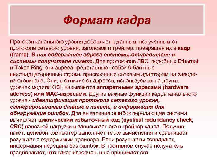 Frame Format The link layer protocol adds a header and a trailer to the data received from the network layer protocol, turning it into a frame. They contain the addresses of the sending system and the receiving system of the packet. For LAN protocols like Ethernet and Token Ring, these addresses are 6-byte hexadecimal strings assigned to network adapters at the factory. They, unlike the addresses used at other levels of the OSI model, are called hardware addresses (hardware address) or MAC addresses. Other important functions of the MAC layer frame are the identification of the network layer protocol that generated the data in the packet, and information for error detection. To detect errors, the transmitting system calculates a cyclic redundancy check (CRC) of the payload and writes it to the frame trailer. Upon receiving the packet, the target computer performs the same calculations and compares the result with the contents of the trailer. If the results match, the information was transmitted without error. Otherwise, the recipient assumes that the packet is corrupt and does not accept it.
 Network Media Access Control Computers on a LAN typically use a shared half-duplex network media. In this case, it is quite possible that two computers will start transmitting data at the same time. In such cases, a kind of packet collision occurs, a collision (collision), in which the data in both packets is lost. One of the main functions of the link-layer protocol is media access control (MAC), i.e., control over data transmission by each of the computers and minimizing packet collisions. The media access control mechanism is one of the most important characteristics of a link layer protocol. Ethernet uses Carrier Sense Multiple Access with Collision Detection (CSMA/CD) to control media access. Some other protocols, such as Token Ring, use token passing.
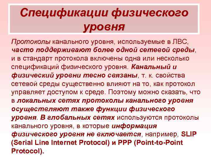 Physical Layer Specifications Link layer protocols used on LANs often support more than one network medium, and one or more physical layer specifications are included in the protocol standard. The data link and physical layers are closely related, because the properties of the network medium significantly affect how the protocol controls access to the medium. Therefore, we can say that in local networks the link layer protocols also perform the functions of the physical layer. WANs use link layer protocols that do not include physical layer information, such as SLIP (Serial Line Internet Protocol) and PPP (Point-to-Point Protocol).
 Network Layer Network layer protocols are responsible for end-to-end communications, while link layer protocols operate only within the LAN. The network layer protocols fully ensure the transmission of the packet from the source to the target system. Depending on the type of network, the sender and receiver may be on the same LAN or on different LANs. For example, when communicating with a server on the Internet, on the way to it, packets created by a computer pass through dozens of networks. By adapting to these networks, the link layer protocol will change many times, but the network layer protocol will remain the same all the way. The cornerstone of the TCP/IP (Transmission Control Protocol/Internet Protocol) protocol suite and the most commonly used network layer protocol is IP (Internet Protocol). Novell Net. Ware has its own IPX (Internetwork Packet Exchange) network protocol, while smaller Microsoft Windows networks typically use the Net protocol. BIOS. Most of the features attributed to Net. The BIOS to the network layer are determined by the capabilities of the IP protocol.
 Addressing The network layer protocol header, like the link layer protocol header, contains fields with the addresses of the source and target systems. However, in this case, the target system address belongs to the final destination of the packet and may differ from the destination address in the link layer protocol header. For example, in a packet generated by a computer to a Web server, the address of the Web server is indicated as the address of the target system at the network level, while at the link level the address of the router in your LAN that provides Internet access indicates the target system. IP uses its own addressing system, which is completely independent of link layer addresses. Each computer on an IP network is manually or automatically assigned a 32-bit IP address that identifies both the computer itself and the network on which it resides. In IPX, the hardware address is used to identify the computer itself, in addition, a special address is used to identify the network in which the computer is located. In Net. The BIOS of computers differ by Net. The BIOS names assigned to each system during installation.
 Fragmentation Network layer datagrams have to traverse multiple networks on their way to their destination, encountering the specific properties and limitations of various link layer protocols in the process. One such limitation is the maximum packet size allowed by the protocol. For example, a Token Ring frame can be up to 4500 bytes, while an Ethernet frame can be up to 1500 bytes. When a large datagram generated on a Token Ring network is transferred to an Ethernet network, the network layer protocol must break it into multiple fragments no larger than 1500 bytes. This process is called fragmentation. In the process of fragmentation, the network layer protocol breaks the datagram into fragments, the size of which corresponds to the capabilities of the link layer protocol used. Each fragment becomes its own package and continues on its way to the target network layer system. The source datagram is formed only after all the fragments have reached the destination. Sometimes, on the way to the target system, the fragments into which a datagram is broken must be re-fragmented.
 Routing Routing is the process of selecting the most efficient route on the Internet to carry datagrams from a source system to a destination system. In complex internetworks, such as the Internet or large corporate networks, there are often multiple paths to get from one computer to another. Routers connect separate LANs that are part of the Internet. The purpose of a router is to receive incoming traffic from one network and forward it to a specific system on another. Internetworks distinguish between two types of systems: end systems and intermediate systems. End systems are senders and receivers of packets. The router is an intermediate system. End systems use all seven layers of the OSI model, while packets arriving at intermediate systems do not rise above the network layer.
 Routing To correctly route a packet to its destination, routers maintain tables of network information (routing tables) in memory. This routing) information can be entered manually by the administrator (static routing) or collected automatically (dynamic routing) from other routers using specialized protocols (dynamic routing protocols). A typical routing table entry contains the address of another network and the address of the router through which the packets must reach that network. In addition, the element of the routing table contains a route metric, a conditional estimate of its effectiveness. If there are multiple routes to a system, the router chooses the most efficient one and sends the datagram to the link layer for transmission to the router specified in the table entry with the best metric. In large networks, routing can be an extraordinarily complex process, but more often than not, it is done automatically and transparently to the user.
 Transport Layer Protocol Identification Just as the link layer header identifies the network layer protocol that generated and transmitted the data, the network layer header contains information about the transport layer protocol from which the data was received. Based on this information, the receiving system forwards incoming datagrams to the appropriate transport layer protocol.
 Transport Layer The functions performed by the transport layer protocols complement those of the network layer protocols. Often the protocols of these levels used for data transmission form an interconnected pair, which can be seen in the example of TCP / IP: the TCP protocol operates at the transport level, IP - at the network level. Most protocol suites have two or more transport layer protocols that perform different functions. An alternative to TCP (Transmission Control Protocol) is UDP (User Datagram Protocol). The IPX protocol suite also includes several transport layer protocols, including NCP (Net. Ware Core Protocol) and SPX (Sequenced Packet Exchange).
 Connection-Oriented Protocols The difference between transport-layer protocols in a particular set is that some of them are connection-oriented and others are not. Systems using a connection-oriented protocol exchange messages by data transfer to establish communication with each other. This ensures that the systems are on and ready to go. The TCP protocol, for example, is connection oriented. When using a browser to connect to an Internet server, the browser and the server first perform a so-called three-way handshake to establish a connection. Only after that the browser sends the address of the desired Web page to the server. When the data transfer is completed, the systems perform the same handshake to end the connection. In addition, connection-oriented protocols perform additional actions, such as sending a packet acknowledgment signal, segmenting data, controlling flow, and detecting and correcting errors. This is why these protocols are often referred to as reliable.
 Connectionless Protocols A connectionless protocol does not establish a connection between two systems before data is transferred. The sender simply transmits the information to the target system, without worrying about whether it is ready to receive data and whether this system even exists. Systems typically resort to connectionless protocols such as UDP for short transactions consisting of only requests and responses. The response signal from the receiver implicitly functions as a transmission acknowledgment signal. Transport layer protocols (as well as network and link layers) usually contain information from higher layers. For example, TCP and UDP headers include port numbers that identify the application that originated the packet and the application to which it is destined.
 The session layer At the session layer, a significant discrepancy between the actual protocols used and the OSI model begins. Unlike the lower layers, there are no dedicated session layer protocols. The functions of this layer are integrated into protocols that also perform the functions of the presentation and application layers. The transport, network, data link and physical layers are responsible for the actual transmission of data over the network. The protocols of the session and higher levels have nothing to do with the communication process. The session layer includes 22 services, many of which define how information is exchanged between systems in the network. The most important services are dialogue management and dialogue separation.
 Presentation layer The presentation layer has only one function: translation of syntax between different systems. Sometimes computers on a network use different syntaxes. The presentation layer allows them to "agree" on a common syntax for exchanging data. When establishing a connection at the presentation layer, the systems exchange messages with information about what syntaxes they have and select the one that they will use during the session. Both systems involved in a connection have an abstract syntax, their native form of communication. The abstract syntaxes of different computer platforms may differ. During the system negotiation process, a common data transfer syntax is chosen. The transmitting system converts its abstract syntax to the data transfer syntax, and the receiving system, upon completion of the transfer, vice versa. If necessary, the system can choose a data transfer syntax with additional features, such as data compression or data encryption.
 The application layer is the entry point through which programs access the OSI model and network resources. Most application layer protocols provide network access services. For example, Simple Mail Transfer Protocol (SMTP) is used by most email programs to send messages. Other application layer protocols, such as FTP (File Transfer Protocol), are themselves programs. Application layer protocols often include session and presentation layer functions. As a result, a typical protocol stack contains four separate protocols that operate at the application (HTTP), transport (TCP), network (IP), and data link (Ethernet) layers.
 A network topology is a diagram of how computers and other network devices are connected using a cable or other network medium. The network topology is directly related to the type of cable used. You cannot select a specific type of cable and use it on a network with an arbitrary topology. However, you can create multiple LANs with different cables and topologies and connect them using bridges, switches, and routers. When choosing cable and other network components, topology will always be one of the most important criteria. The main network topologies are "bus" (bus), "star" (star) and "ring" (ring). Additional topologies "hierarchical star" (hierarchical star), cellular (mesh) and wireless topologies (wireless) - "each with each" (ad hoc), and infrastructure (infrastructure).
 Bus topology A bus topology is a common cable (called a bus or backbone) to which all workstations are connected. There are terminators at the ends of the cable to prevent signal reflection.
 Bus topology Benefits Short network setup time; Cheap (requires less cable and network devices); Easy to set up; The failure of a workstation does not affect the operation of the network. Disadvantages Any problems in the network, such as a cable break, failure of the terminator completely destroy the operation of the entire network; Complex localization of faults; With the addition of new workstations, network performance drops.
 Star topology Star topology is the basic topology of a computer network in which all computers on the network are connected to a central node (usually a network hub), forming a physical network segment. Such a network segment can function both separately and as part of a complex network topology (usually a "tree" (hierarchical star)).
 Topology "star" Advantages failure of one workstation does not affect the operation of the entire network as a whole; good network scalability; easy troubleshooting and breaks in the network; high network performance (subject to proper design); flexible administration options. Disadvantages failure of the central hub will result in the inoperability of the network (or network segment) as a whole; networking often requires more cable than most other topologies; the finite number of workstations in a network (or network segment) is limited by the number of ports in the central hub.
 Tree or Hierarchical Star Topology A star topology can be extended by adding a second hub, and sometimes a third or fourth. To connect a second hub to a star topology network, you need to connect it to the first hub using a regular cable and a special uplink port on one of the hubs. A typical 10 Mbps Ethernet network can include up to four hubs, while a Fast Ethernet network can typically only have two.
 Logical Ring Topology The cables in a ring topology network are also connected to a hub, making it look like a star. The network "ring" (Token Ring) is implemented logically by connecting wires inside the cables and a special hub - the multiple access unit (MSAU). It receives data through one port and transmits it in turn through all the others (not simultaneously, like an Ethernet hub).
 Physical ring topology Among the popular network protocols, there is one - FDDI (Fiber Distributed Data Interface) - which allows the connection of cables into a physical ring. This ring should consist of two separate physical rings, traffic on which is transmitted in opposite directions. If computers are connected to both rings, the network can function even if one of them fails.
 Ring Topology Benefits Easy to install; Almost complete absence of additional equipment; The possibility of stable operation without a significant drop in data transfer rate during heavy network load, since the use of a marker eliminates the possibility of collisions. Disadvantages Failure of one workstation, and other problems (cable break), affect the performance of the entire network; Difficulty in configuring and customizing; Difficulty in troubleshooting.
 The mesh topology of computer networks exists more as a theoretical concept than as a practical implementation. In a mesh network, all computers are connected to each other by separate connections. In reality, this topology is implemented so far only in networks with two nodes. With an increase in the number of computers in the network, each of them would have to be equipped with network interfaces according to the number of other computers.
 Ad Hoc Wireless Topology In Ad Hoc mode, clients communicate directly with each other. A peer-to-peer communication is established in a point-to-point manner, and computers communicate directly without the use of access points. This creates only one service area that does not have an interface for connecting to a wired LAN. The main advantage of this mode is ease of organization: it does not require additional equipment (access points). The mode can be used to create temporary networks for data transmission.
 Infrastructure wireless topology In this mode, access points provide communication between client computers. The access point can be thought of as a wireless switch. Client stations do not communicate directly with each other, but communicate with the access point, and it already sends packets to the recipients.


 Coaxial cable Coaxial cable (from Latin co - together and axis - axis, that is, "coaxial") - a type of electrical cable designed to transmit high-frequency signals. The coaxial cable has an inner conductor of copper or copper-plated steel, an inner dielectric of foamed polyethylene and a shield of foil and, in some cases, a steel braid. Some cables have two layers of foil as a screen, between which there is a steel braid. Due to the coincidence of the centers of both conductors, as well as a certain ratio between the diameter of the central core and the screen, a standing wave mode is formed inside the cable, which makes it possible to reduce signal losses due to radiation to almost zero. At the same time, the screen provides protection against external electromagnetic interference.
 Coaxial cable Cables are divided according to the Radio Guide scale. The most common cable categories: RG-8 and RG-11 - "Thick Ethernet" (Thicknet), 50 Ohm. Standard 10 BASE 5; RG-58 - "Thin Ethernet" (Thinnet), 50 Ohm. Standard 10 BASE 2: RG 58/U - solid center conductor, RG 58 A/U - stranded center conductor, RG 58 C/U - military cable; RG-59 - television cable (Broadband/Cable Television), 75 Ohm. Russian equivalent of RK 75 x x (“radio frequency cable”); RG-6 - television cable (Broadband/Cable Television), 75 Ohm. Category RG 6 cable has several varieties that characterize its type and material. Russian analogue of RK 75 x x;
 Coaxial cable RG-11 trunk cable, almost indispensable if you need to solve the problem with long distances. This type of cable can be used even at distances of about 600 m. The reinforced outer insulation makes it possible to use this cable without problems in difficult conditions (street, wells). There is a variant S 1160 with a cable, which is used for reliable transmission of a cable through the air, for example, between houses; RG-62 - ARCNet, 93 Ohm RG-8 RG-58
 "Thin" Ethernet Was the most common cable for building local networks. With a diameter of approximately 6 mm and considerable flexibility, it could be laid in almost any place. The cables were connected to each other and to the network card in the computer using a BNC T-connector (Bayonet Neill-Concelman). Between themselves, the cables could be connected using an I-connector BNC (direct connection). Terminators must be installed at both ends of the segment. Supports data transfer up to 10 Mbps over distances up to 185 m. I BNC connector BNC terminator T BNC connector
 "Thick" Ethernet Thicker than the previous cable - about 12 mm in diameter, had a thicker center conductor. Poorly bent and had a significant cost. In addition, there were some difficulties in connecting to a computer - AUI (Attachment Unit Interface) transceivers were used, connected to the network card using a branch penetrating the cable, the so-called. "vampires". Due to the thicker conductor, data transmission could be carried out over a distance of up to 500 m at a speed of 10 Mbps. However, the complexity and high cost of installation did not give this cable such a wide distribution as RG 58. Historically, the proprietary RG 8 cable had a yellow color, and therefore you can sometimes see the name "Yellow Ethernet" (English Yellow Ethernet).
 Twisted pair Vita I pair (eng. twisted pair) - a type of communication cable, is one or more pairs of insulated conductors twisted together (with a small number of turns per unit length), covered with a plastic sheath. The twisting of conductors is carried out in order to increase the connection of the conductors of one pair (electromagnetic interference equally affects both wires of the pair) and the subsequent reduction of electromagnetic interference from external sources, as well as mutual interference during signal transmission. To reduce the coupling of individual cable pairs (periodic convergence of conductors of different pairs), in UTP cables of category 5 and above, the wires of the pair are twisted with different pitches. Twisted pair is one of the components of modern structured cabling systems. Used in telecommunications and computer networks as a network carrier in many technologies such as Ethernet, Arcnet and Token ring. Currently, due to its low cost and ease of installation, it is the most common solution for building local networks.
 Cable types twisted pair Depending on the presence of protection - electrically grounded copper braid or aluminum foil around twisted pairs, the types of this technology are determined: unprotected twisted pair (UTP - Unshielded twisted pair) - there is no protective screen around a separate pair; foil twisted pair (FTP - Foiled twisted pair) - also known as F / UTP, there is one common external screen in the form of a foil; protected twisted pair (STP - Shielded twisted pair) - there is protection in the form of a screen for each pair and a common external screen in the form of a grid; foil shielded twisted pair (S / FTP - Screened Foiled twisted pair) - an external screen made of copper braid and each pair in a foil braid; unprotected shielded twisted pair (SF / UTP - Screened Foiled Unshielded twisted pair) - a double outer shield made of copper braid and foil, each twisted pair is unprotected.
 Twisted Pair Cable Categories There are several categories of twisted pair cable, numbered CAT 1 to CAT 7, that determine the effective frequency range to pass. Higher category cable usually contains more pairs of wires and each pair has more turns per unit length. The categories of unshielded twisted pair are described in the EIA/TIA 568 standard (American Wiring Standard for Commercial Buildings). CAT 1 (frequency band 0.1 MHz) - a telephone cable, only one pair (in Russia a cable is used and no twists at all - “noodles” - it has no worse characteristics, but more interference). In the USA it was used earlier, only in a "twisted" form. Used only for voice or data transmission using a modem. CAT 2 (frequency band 1 MHz) - an old type of cable, 2 pairs of conductors, supported data transfer at speeds up to 4 Mbps, used in Token ring and Arcnet networks. Now sometimes found in telephone networks.
 Cable categories twisted pair CAT 3 (frequency band 16 MHz) - 4 pair cable, used in the construction of local networks 10 BASE-T and token ring, supports data transfer rates up to 10 Mbps or 100 Mbps using 100 BASE-T technology 4. Unlike the previous two, it meets the requirements of the IEEE 802 standard. 3. Also still found in telephone networks. CAT 4 (frequency band 20 MHz) - the cable consists of 4 twisted pairs, used in token ring, 10 BASE-T, 100 BASE-T 4 networks, the data transfer rate does not exceed 16 Mbps over one pair, is not used now. CAT 5 (frequency band 100 MHz) - 4-pair cable, used in the construction of local networks 100 BASE-TX and for laying telephone lines, supports data transfer rates up to 100 Mbps when using 2 pairs.
 Category cable twisted pair CAT 6 (frequency band 250 MHz) - used in Fast Ethernet and Gigabit Ethernet networks, consists of 4 pairs of conductors and is capable of transmitting data at speeds up to 1000 Mbps. Added to the standard in June 2002. According to IEEE, 70% of installed networks in 2004 used CAT 6 cable. it is planned to be used for applications running at speeds up to 40 Gigabit/s. Added to the standard in February 2008. CAT 7 - the specification for this type of cable is approved only by the international standard ISO 11801, data transfer rate up to 100 Gbps, signal transmission frequency up to 600-700 MHz. This category of cable has an overall shield and shields around each pair. The seventh category, strictly speaking, is not UTP, but S / FTP (Screened Fully shielded Twisted Pair).
 The 8 P 8 C (8 Position 8 Contact) twisted pair connector, often erroneously called RJ 45 or RJ-45, is a unified connector used in telecommunications that has 8 pins and a latch. Used to create a LAN using 10 BASE-T, 100 BASE-T and 1000 BASE-TX technologies using 4 pairs of twisted pair cables. It is used in many other areas and for building other networks. The telephone unified RJ-11 connector is smaller and can be inserted into sockets 8 P 8 C (for backwards compatibility). 8 P 8 C (RJ 45) Twisted pair
 An optical fiber is a glass or plastic filament used to carry light within itself through total internal reflection. Optical fiber is used as a medium for long-distance communication and building a computer network, due to its flexibility (albeit less than conductive cables). Although the fibers can be made from transparent ductile fiber or quartz fiber, those used to transmit information over long distances are made from quartz glass due to the low optical attenuation of electromagnetic radiation. In communication, multimode and single-mode fibers are used; multi-mode fiber is typically used for short distances (up to 500 m), and single-mode fiber for long distances. Due to the tight tolerance between single mode fiber, transmitter, receiver, amplifier and other single mode components, they are usually more expensive to use than multimode components.
 Optical fiber A light pulse, passing through the fiber, will change its shape due to the phenomenon of dispersion - it will “smear”. There are several types of dispersion: modal, material and waveguide. Modal dispersion is inherent in a multimode fiber and is due to the presence of a large number of modes, the propagation time of which is different. Material dispersion is due to the dependence of the refractive index on the wavelength. Waveguide dispersion is caused by processes inside the mode and is characterized by the dependence of the mode propagation velocity on the wavelength.
 Optical fiber Single-mode SCS fiber has a core diameter of 8-10 µm. To identify an optical cable with single-mode fibers, the inscriptions 9/125 or 8 -10/125 can be found on the cable or in the description of the optical cable. When designating a single-mode fiber, two letters SM are used (English acronym for the word Single. Mode). For multimode fibers, the outer diameter of the core can be 50 µm or 62.5 µm. When describing an optical cable with multimode fibers, the following designations can be found 50/125, 62.5/125, where 50 and 62.5 is the diameter of the fiber core. You can also find two letters MM (an acronym for the word Multi. Mode) when designating a multimode fiber.
 Fiber optic connector ST ST. From the English straight tip connector (straight connector) or, informally, Stick-and-Twist (insert and turn). It was developed in 1985 by AT&T, now Lucent Technologies. The design is based on a ceramic tip (ferule) with a diameter of 2.5 mm with a convex end surface. The plug is secured to the socket by a spring-loaded bayonet element (similar to BNC connectors used for coaxial cable).
 ST fiber optic connector ST connectors are the cheapest and most common type in Russia. It is slightly better than the SC in terms of tough environments thanks to its simple and strong metal construction (allows more room for brute force). As the main disadvantages, one can name the complexity of marking, the laboriousness of connection, and the impossibility of creating a duplex plug.
 Fiber optic connector SC SC. From the English subscriber connector (subscriber connector), and sometimes the unofficial decryption Stick-and-Click (insert and snap) is used. It was developed by the Japanese company NTT, using the same ceramic tip as in ST, with a diameter of 2.5 mm. But the main idea is a lightweight plastic body that protects the tip well and provides smooth connection and disconnection in one linear motion. This design allows a high density of mounting, and easily adapts to convenient dual connectors. Therefore, SC connectors are recommended for creating new systems, and are gradually replacing ST.
 Other fiber connectors In addition, two more types should be noted, one of which is used in the related industry, and the other is gradually gaining popularity. FC. Very similar to ST, but with a threaded lock. It is actively used by telephonists of all countries, but practically does not occur in local networks. LC. New "miniature" connector, structurally identical to SC. So far, it is quite expensive, and its use is meaningless for "cheap" networks. As the main argument "for" the creators cite a high density of editing. This is a serious enough argument, and in the distant (by telecommunications standards) future it is quite possible that it will become the main type.
 Network Equipment Cable Types Network Adapter Network Hub Network Bridge Network Switch Network Router
 A network card also known as a network card, network adapter, Ethernet adapter, NIC (English network interface controller) is a peripheral device that allows a computer to interact with other network devices. According to the constructive implementation, network cards are divided into: internal - separate cards inserted into a PCI, ISA or PCI E slot; external, connected via USB or PCMCIA interface, mainly used in laptops; built into the motherboard.
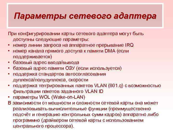 Network adapter options When configuring the network adapter card, the following options may be available: IRQ hardware interrupt request line number DMA channel number (if supported) base I/O address base RAM address (if used) duplex auto-negotiation/ half duplex, speed support for tagged VLAN packets (801. q) with the ability to filter packets of a given VLAN ID WOL (Wake on LAN) parameters Depending on the power and complexity of the network card, it can implement computing functions (mainly counting and generating frame checksums) in hardware or programmatically (by a network card driver using a central processor).
 Characteristics of network adapters A network adapter (Network Interface Card, NIC), together with its driver, implements the second, link level of the open systems model in the end node of the network - a computer. More precisely, in a network operating system, the adapter/driver pair performs only the functions of the physical and MAC layers, while the LLC layer is usually implemented by an operating system module that is common to all drivers and network adapters. Actually, this is how it should be in accordance with the IEEE 802 protocol stack model. For example, in Windows NT, the LLC level is implemented in the NDIS module, which is common to all network adapter drivers, regardless of which technology the driver supports.
 Functions of network adapters The network adapter, together with the driver, performs two operations: transmitting and receiving a frame. Transferring a frame from a computer to a cable consists of the following steps (some may be omitted, depending on the coding methods adopted): 1. Reception of an LLC data frame through an interlayer interface, along with MAC layer address information. Usually, interaction between protocols inside a computer occurs through buffers located in RAM. Data for transmission to the network is placed in these buffers by upper-layer protocols that retrieve them from disk memory or from the file cache using the I / O subsystem of the operating system. 2. Formulation of a MAC layer data frame into which the LLC frame is encapsulated (with flags 01111110 discarded). Filling in the destination and source addresses, calculating the checksum.
 Functions of network adapters 3. Formation of symbols of codes when using redundant codes such as 4 V/5 V. Scrambling of codes to obtain a more uniform spectrum of signals. This stage is not used in all protocols - for example, 10 Mbps Ethernet technology does without it. 4. Output of signals to the cable in accordance with the accepted line code - Manchester, NRZ 1. MLT 3, etc.
 Functions of network adapters Reception of a frame from a cable to a computer includes the following actions: 1. Reception from a cable of signals that encode a bit stream. 2. Identification of signals against the background of noise. This operation can be performed by various specialized chips or DSP signal processors. As a result, a certain bit sequence is formed in the adapter's receiver, with a high degree of probability coinciding with the one that was sent by the transmitter.
 Functions of network adapters 3. If the data was scrambling before being sent to the cable, then it is passed through a descrambler, after which the code symbols sent by the transmitter are restored in the adapter. 4. Verification of the frame checksum. If it is incorrect, then the frame is discarded, and the corresponding error code is transmitted to the LLC protocol through the interlayer interface upwards. If the checksum is correct, then the LLC frame is extracted from the MAC frame and transmitted through the inter-layer interface upstream, to the LLC protocol. The LLC frame is buffered in RAM. The distribution of responsibilities between the network adapter and its driver is not defined by standards, so each manufacturer decides this issue on its own. Typically, network adapters are divided into adapters for client computers and adapters for servers.
 Classification of network adapters In adapters for client computers, much of the work is shifted to the driver, thereby making the adapter simpler and cheaper. The disadvantage of this approach is the high degree of loading of the computer's central processor with routine work on transferring frames from the computer's RAM to the network. The central processor is forced to do this work instead of performing user application tasks. Therefore, adapters designed for servers usually have their own processors, which do most of the work of transferring frames from RAM to the network and vice versa. An example of such an adapter is the SMS Ether network adapter. Power with integrated Intel i 960 processor.
 Network hub or Hub (jar. from the English hub - center of activity) - a network device designed to combine several Ethernet devices into a common network segment. Devices are connected using twisted pair, coaxial cable or fiber. The hub works at the physical layer of the OSI network model, repeats the signal coming to one port to all active ports. If a signal arrives at two or more ports, a collision occurs at the same time, and the transmitted data frames are lost. Thus, all devices connected to the hub are in the same collision domain. Hubs always operate in half-duplex mode, all connected Ethernet devices share the provided access bandwidth.
 Characteristics of network hubs The number of ports - connectors for connecting network lines, hubs are usually produced with 4, 5, 6, 8, 16, 24 and 48 ports (the most popular with 4, 8 and 16). Hubs can be cascaded to each other, increasing the number of ports on a network segment. Some have special ports for this. Data transfer rate - measured in Mbps, hubs are available with speeds of 10, 100 and 1000. Hubs with the ability to change the speed are mainly common, referred to as 10/1000 Mbps. Typically, if at least one device is attached to a hub at a low range speed, it will send data to all ports at that speed. The type of network media is usually twisted pair or fiber, but there are hubs for other media, as well as mixed media, such as twisted pair and coaxial cable.


 Twisted Pair Crimp Diagrams The twisted pair crimp diagrams are for Category 5 cable (4 pairs of conductors). It is crimped with an 8 P 8 C connector. There are 2 cable crimping schemes: a straight cable and a crossed (cross-over) cable. The first scheme is used to connect a computer to a switch / hub, the second one is used to connect 2 computers directly and to connect some old models of hubs / switches (uplink port). Connector numbering 8 P 8 C
 Crimping patterns EIA/TIA 568 A straight cable EIA/TIA 568 B straight cable


 Network Equipment Cable Types Network Adapter Network Hub Network Bridge Network Switch Network Router
 Network bridge Bridge, network bridge, bridge (slang, tracing paper from English bridge) - network equipment for connecting segments of a local network. The network bridge operates at the second layer of the OSI model, providing collision domain limitation (in the case of an Ethernet network). A formal description of a network bridge is given in the IEEE 802.1 D standard.
 Bridge functionality limitation of the collision domain delay of frames addressed to a node in the sender segment limitation of transition from domain to domain of erroneous frames: dwarfs (frames less than the length allowed by the standard (64 bytes)) frames with errors in the CRC frames with the "collision" attribute prolonged frames (larger than allowed by the standard)
 Bridge functionality Additional functionality Loop detection (and suppression) (broadcast storm) Spanning tree protocol support to break loops and provide link redundancy.
 Network Equipment Cable Types Network Adapter Network Hub Network Bridge Network Switch Network Router
 A network switch or switch (slang from the English switch - switch) is a device designed to connect several nodes of a computer network within one segment. Unlike a hub that distributes traffic from one connected device to all others, a switch only forwards data directly to the recipient. This improves network performance and security by removing the need (and ability) for the rest of the network to process data that was not intended for them. The switch operates at the link layer of the OSI model, and therefore, in the general case, it can only unite nodes of the same network by their MAC addresses.
 How the Switch Works The switch maintains a table in memory that maps the host's MAC address to the switch's port. When the switch is powered on, this table is empty and it is in learning mode. In this mode, incoming data on any port is transmitted to all other ports of the switch. In this case, the switch analyzes the frames and, having determined the MAC address of the sender's host, enters it into a table. Subsequently, if one of the switch ports receives a frame destined for a host whose MAC address is already in the table, then this frame will be transmitted only through the port specified in the table.
 Switching Modes There are three switching modes. Each of them is a combination of parameters such as latency and transmission reliability. 1. With intermediate storage (Store and Forward). The switch reads all the information in the frame, checks it for errors, selects a switching port, and then sends the frame to it. 2. Through (cut-through). The switch reads only the destination address in the frame and then switches. This mode reduces transmission delays, but it does not have an error detection method.
 Switching modes 3. Fragment-free or hybrid. This mode is a modification of the through mode. Transmission is carried out after filtering fragments of collisions (64-byte frames are processed using the store and forward technology, the rest are processed using the cut through technology).
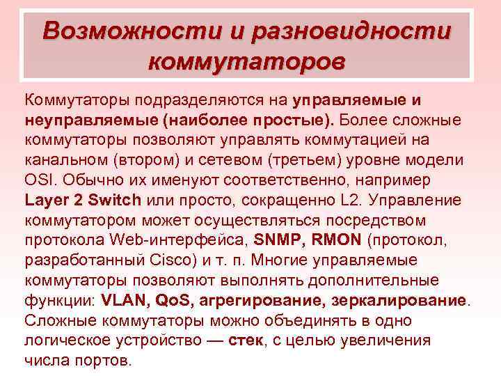 Features and types of switches Switches are divided into managed and unmanaged (the most simple). More complex switches allow you to control switching at the channel (second) and network (third) level of the OSI model. They are usually named accordingly, for example, Layer 2 Switch or simply L 2 for short. The switch can be managed through the Web interface protocol, SNMP, RMON (a protocol developed by Cisco), etc. Many managed switches allow you to perform additional functions: VLAN, Qo . S, aggregation, mirroring. Complex switches can be combined into one logical device - a stack, in order to increase the number of ports.

 Router A router or a router, a router (from the English router), is a network device that, based on information about the network topology and certain rules, makes decisions about forwarding network layer packets (layer 3 of the OSI model) between different network segments. Works at a higher level than the switch and network bridge.
 How a Router Works The router uses the destination address specified in the data packets and uses the routing table to determine the path that the data should take. If there is no described route in the routing table for the address, the packet is dropped. There are other ways to determine the packet forwarding path, such as using the source address, upper layer protocols used, and other information contained in network layer packet headers. Routers can filter the transit data flow based on certain rules in order to restrict access, encrypt / decrypt transmitted data, etc.
 The routing table contains information on the basis of which the router makes a decision about further forwarding of packets. The table consists of a number of entries - routes, each of which contains the address of the recipient's network, the address of the next node to which packets should be transmitted and some entry weight - a metric. The metrics of the entries in the table play a role in calculating the shortest routes to various destinations. Depending on the router model and the routing protocols used, the table may contain some additional service information.
 Routing table 192.168.64.0/16 via 192.168.1.2, 00:34, Fast. Ethernet 0/0. 1 where 192.168.64.0/16 is the destination network, 110/administrative distance /49 is the route metric, 192.168.1.2 is the address of the next router to forward packets to for network 192.168.64.0 /16, 00:34 - the time during which this route was known, Fast. Ethernet 0/0. 1 - router interface through which you can reach the "neighbor" 192. 168. 1. 2.
 Static routing The routing table can be compiled in two ways: static routing - when entries in the table are entered and changed manually. This method requires administrator intervention every time there is a change in the network topology. On the other hand, it is the most stable and requires a minimum of router hardware resources to serve the table.
 Dynamic Routing dynamic routing - when entries in the table are updated automatically using one or more routing protocols - RIP, OSPF, EIGRP, IS-IS, BGP, etc. In addition, the router builds a table of optimal paths to destination networks based on various criteria - the number of intermediate nodes, channel bandwidth, data transfer delay, etc. The criteria for calculating optimal routes most often depend on the routing protocol, and are also set by the router configuration. Often, graph theory is used to build routing tables.
 Using Routers Routers help reduce network congestion by dividing the network into collision and broadcast domains, and by filtering packets. They are mainly used to combine networks of different types, often incompatible in architecture and protocols, for example, to combine Ethernet LANs and WAN connections using the x protocols. DSL, PPP, ATM, Frame relay, etc. Often, a router is used to provide access from a local network to the global Internet, performing the functions of address translation and a firewall.
 Router Implementation A router can be either a dedicated (hardware) device or a regular computer that functions as a router. There are several software packages (mostly based on the Linux kernel) that can turn a PC into a multifunctional router, such as GNU Zebra.
 Collision domain Collision domain is a network segment that has a common physical layer, in which only one subscriber can access the transmission medium at a time. The delay in signal propagation between stations, or the simultaneous start of transmission, causes collisions that require special handling and reduce network performance. The more nodes in such a segment, the higher the probability of collisions. The collision domain is reduced by segmenting the physical network using bridges and other higher-level network devices.
 Collision domain Network devices operating at different levels of the OSI model can extend or limit the collision domain. The following options are possible: OSI layer 1 devices (hubs, repeaters) only retransmit any signal coming from the transmission medium and extend the collision domain. Devices of the second and third OSI layers (bridges, switches, routers) limit the collision domain. A collision domain does not exist when connecting to a switch port in full duplex mode, or when connecting point-to-point between two network adapters.
 Broadcast domain Broadcast domain (segment) is a logical section of a computer network in which each device can transmit data directly to any other device without using a router. In the general case, this term is applicable to the second (link) layer of the OSI network model, but sometimes it is also applied to the third layer with a corresponding reservation. Devices that restrict the broadcast domain - routers operating at the third, network layer of the OSI model, and switches at the second layer of the OSI model that support VLAN technology. First-level devices - hubs and repeaters, as well as switches without VLAN support, do not limit the broadcast domain.
 Data transfer schemes Unicast (one-way (one-way)) data transfer implies the transmission of packets to a single destination.
 Data transfer schemes Broadcast is a form of data transfer in which each transmitted data packet reaches all network participants simultaneously. Broadcasting is possible only within one network segment (L 2 or L 3), however, data packets can be sent from outside the segment in which the broadcast will take place (for example, sending a packet to a broadcast IP address through a router from outside the network). The network load in the case of broadcast is no different from a normal data transmission to one destination, since data packets are not multiplied (unlike multicast).
 Data transfer schemes Multicast (English multicast) is a special form of broadcasting, in which copies of packets are sent to a certain subset of recipients. With traditional IP addressing technology, each recipient of information needs to send their own data packet, that is, the same information is transmitted many times. Multicast technology is an extension of IP addressing that allows one copy of a packet to be sent to all recipients at once. The set of recipients is determined by the belonging of each of them to a particular group. Only members of that group receive mailings for a specific group.
 Data transmission schemes To implement multicast addressing in a local network, the following is required: support for multicast addressing by the TCP/IP protocol stack; software support for the IGMP protocol to send a request to join a group and receive group traffic; support for multicast network card; application that uses multicast, such as video conferencing. To expand this capability to the global network, it is additionally necessary to support multicast addressing by all intermediate routers and pass multicast traffic by the firewalls used. On a LAN, you can achieve even greater optimization by using switches with multicast filtering, which automatically configures itself to pass traffic only to recipients.
 Data Transfer Schemes IP Multicast uses addresses from 224.0.0.0 to 239.255. Both static and dynamic addressing are supported. An example of static addresses is 224.0.0.1 - the address of a group that includes all nodes of the local network, 224.0.0.2 - all routers of the local network. The address range 224.0.0.0 to 224.0.0.255 is reserved for routing protocols and other low-level multicast support protocols. The rest of the addresses are dynamically used by applications. Recently, multimedia broadcasts and video conferencing have become widespread. With traditional technology, the bandwidth of existing channels is only enough to establish communication with a very limited number of recipients. Multicast addressing removes this restriction and there can be any number of recipients.
 Data Transfer Schemes Anycast (literally "sending to someone") is a packet distribution method (implemented, in particular, in the IPv 6 protocol), which allows a device to send data to the nearest of a group of recipients. In the IP protocol, anycast is implemented by publishing the same route from different points in the network through the BGP protocol. Anycast is currently used on the Internet to improve response times and load balance NS root servers. For example, the root NS server K has many installations, including in Amsterdam, London, Tokyo, Delhi, Miami, Reykjavik, Novosibirsk, Helsinki, and other cities.
Any networks created or laid across any territories with the help of technical means and focused on servicing various categories of users constitute the engineering infrastructure of residential and industrial facilities, cities and states. They have a certain structure that makes it possible to most effectively meet the needs of states, social formations, economic sectors and individuals. In information processes, systems and technologies, the term “network” means at least several computers and other computers connected to each other using special equipment to provide calculations and exchange various types of information. Complex networks imply a large number of users, an extensive structure, switching and communication nodes connecting everyone into a single structure.
Communication network - a system of objects that perform the functions of creating (generation), transforming, storing and consuming a product and transmission lines through which this product is transmitted within the network. The objects of such a system are called points or nodes of the network, and the lines are called communications, connections or communication channels. The product in such networks can be energy, mass and information.
The creation of the first communication computer networks, focused primarily on mathematical calculations, gave rise to their name - " computer networks».
Computing network - a computer communication network designed for measurements, experiments, complex combined mathematical calculations, etc. works, including in automatic and automated systems.
Almost immediately, with the advent of computer networks, they began to be used to exchange various kinds of data (data networks) and information. The development of computer networks and network technologies has shown the possibility of using them to most fully reveal the information essence of networks and organize large-scale information support for society. This led to the fact that computer networks that provide the exchange of information resources began to be called " informational networks." At the same time, it is not supposed to abandon network computing, moreover, this technology is constantly being improved, and now supercomputers united in an information network make it possible to carry out ultra-fast calculations related to the needs of any subject areas.
Information network - a communication network in which information acts as a product of creation, processing, storage and use.
Note that the computing devices used to create networks historically have different names: computers (VM), electronic computers (ECM), mini- and micro-computers, computers, including personal computers (PC), supercomputers, etc. They can also perform specific functions that differ from each other, but in our case we will perceive them as similar devices and use them in the text as synonyms.
So, let's move on to considering the types and types of networks.
By functional affiliation select networks:
● Informational,
● Computing,
● Information and computing.
By data transfer methods there are networks with:
1) data transmission via dedicated communication channels;
2) circuit switching;
3) message switching;
4) switching of packets of messages.
The presented systematization of networks by functional affiliation and methods of data transmission imply their structuring. Network architecture includes three structures:
● logical,
● hardware,
● software.
Consideration logical structure necessary in solving research problems consisting of two types: analysis and synthesis. The logical structure of the network assumes the presence of the following components:
● computers (computers),
● main control computer,
● auxiliary computer,
● communication devices and systems,
● territorial equipment.
The actual network structures may differ from the logical one. In one computer of the network, the functions of the computing, main control and switching machine can be concentrated.
Hardware structure means in this case the network topology considered within the framework of this topic.
Program structure includes the OS, and various software that ensures the interconnection of computers in networks, the transfer of information, protection against unauthorized actions, etc. The software is discussed in topic 8.
The development of computer technology and technologies has brought to life the need to exchange information not only in one organization, but also with other enterprises and individuals located at various distances from each other. This contributed to the development of territorial, regional, international (global) computer systems and the emergence of a worldwide "network of networks" - the Internet. At the same time, it turned out that a computer can be connected to a subscriber telephone network and get access to other subscribers of the Internet, e-mail, teletypes and telefaxes working with this network, etc. In the general case, to create simple but effective automated information technologies, two or three PCs can be used, which, among other things, allow the creation of separate, distributed and integrated resources.
The growth of information systems, interconnected to exchange information and solve other problems, initiated the creation of international networks, and then the Internet. Diverse networks can be physically connected by communication channels, but it is impossible to ensure the functioning of various hardware and software without coordinating the relevant parameters. This circumstance was decisive for the formation of uniform network rules, and then Internet standards, which influenced the creation of Internet technologies.
Under Internet technology is understood as a set of rules and procedures, as a result of which the user receives Internet information resources.
The structure of Internet technology is based on the general structure of networks and consists of the following elements:
● hardware – communication lines and necessary equipment (routers, servers, user systems);
● software - server applications that ensure the functioning of the main network nodes, client software (browsers, email programs, FTP clients);
● organizational support - a hierarchical structure, at the top of which are telecommunications companies that own large communication channels. Below - regional providers, Internet service providers (primary - owning their own communication channels with the core network and secondary - leasing channels from primary providers and regional telecommunications companies).
Any network is characterized by the presence of one or more structures that manage its operation and end users (executors, clients, customers, etc.). In information networks, control systems are called servers.
under the term " server" (eng. " server ”- serving processor, service node) understand a network-connected, sufficiently powerful computer that has certain shared resources, as well as, as a rule, the ability to combine a certain number of computers both in local and global information networks. Servers typically perform administrative functions on the network and are called system administrators. Their tasks include checking the operability of the system (channels, computers, programs, etc.); detection of failures, unauthorized access and other violations in the network; network recovery; accounting for network operation, preparing reports on its operation and providing users with information about network resources.
By appointmentservers are divided into: file, communication, applications, mail, etc.
Historically, the first to appear file server (« File Server ”) and was intended to provide customers with certain programs and files. At the request of users, the file server provides copies of certain software components. Therefore, the server must have powerful storage for all required programs. The operation of a file server largely corresponds to centralized dispatching.
Communication Server provides auxiliary communication functions, laying out the best routes for the delivery of correspondence. To do this, he uses tables: control, the status of network nodes.
Applications server ("Application Server ”) performs all the necessary work, and users deal only with the source data and the result of processing.
Mail serverdesigned to organize e-mail. The mail server software can be installed on any PC with any domain name, even the third or fourth level.
In addition, networks use: a database server (" Data Base Server ”), print server, fax server, etc. The most widely used software is Windows NT.
The computers connected to the network to the servers are called workstations (PCs) or clients. The difference lies in the software used, which allows you to use computers on the network only as a server or as a PC. It is possible that any computer on the network can be a server in some conditions, and a “client” in others. " Client' is generally considered a less powerful computer whose resources are not shared on the network. A network formed from computers "servers" and "clients", based on software that ensures their operation in such modes, is called " client-server».
The main task of the network is the reliable organization of the rapid exchange of information between its subscribers, which is performed by the data transmission system (DTS) organized in this network. The fulfillment of such a goal depends on the chosen network structure, the bandwidth of its channel-forming equipment, the method of data transmission, etc.
The main requirements for networks include: ease of use, high speed of information transfer, low cost and secrecy. Important parameters of networks are also openness, reliability, dynamism, autonomy. In addition, the network is determined by the resources used in it, software and hardware solutions, interface, the possibility of error-free transmission of information, as well as services.
Under interface refers to the way a user accesses network resources. It implies the appearance of presenting information on the computer display screen, the convenience and ease of executing the necessary commands, a friendly menu and a prompt system, a standard method for working with programs, a system for displaying messages that control the functioning of the network (monitoring), the maximum use of natural languages, etc.
From the point of view of the organization, there are three types of networks: real, artificial and peer-to-peer. Let's consider them in more detail.
TO real networks include those in which computers are interconnected according to a certain scheme by means of special devices - network adapters and the presence of specialists who monitor and operate such networks is required. They called "real network or Network With an Attitude" (NWA). For example, Novell's NetWare and Microsoft's Windows NT . More complex and at the same time widespread is the “client / server” network technology, when any computer on the network in certain situations can alternately be both a server and a client. Their IRs are usually located on the hard drives of one or more servers. In any case, wherever a shared IR is located, it is available to all users of that network.
Artificial networks do not require a special network hard drive. Computers on these networks communicate with each other through serial or parallel ports without special network adapters. Sometimes this connection is called null modem or zero-slot (eng. " zero-slot network ”), since no network card (adapter) is included in any of the slots on the computer. These networks are very slow and typically only allow two computers to work at the same time. These include Laplink, Interlink, etc.
Peer-to-peer networks are organized on the principle of "equal among equals" (eng. " peer-to-peer network ”) and belong to an intermediate type between real and artificial. In a peer-to-peer network, depending on the need, each computer can be a server or a PC. For example, a PC with a printer connected to it can be used as a network print server, etc. Firm Microsoft embeds such a network in Windows’95/97/98/2000 operating systems. Company Artisoft offers a peer-to-peer network LANtastic working with operating systems DOS and Windows.
The advantage of such networks is that they provide almost the same features (services) as real networks, while being much easier to install and maintain. In addition, there is no need to uniquely allocate servers, since any computer can be a server and a client at the same time. At the same time, users' computers can access folders, files, and printers located on other computers on this network.
An important aspect of network technologies is the choice network messaging method. Three transmission methods are known and used.
Priority access transmission method . The transmitting computer receives a request to transmit information. He is given a channel for temporary use. All other computers on the network are waiting for the transfer session to end.
Shuttle method . An information packet circulates in the network with an empty interval and sequentially polls all computers for the need to transmit information by them. If there is such a need, the moving interval picks up a possible information packet for transmission and transfers it to the addressee.
Token Packet Method . This method is similar to container transportation, when a message prepared for transmission is “converted” (transformed) into packets with an address and waits for an opportunity with a transporter, which in this case is a marked time interval. This interval can only be used by one computer.
If a single-channel communication system is adopted, then only one RS can transmit data at any time. With a multichannel communication system, the maximum number of transmitted messages is equal to the number of information channels. Such a system allows you to transfer graphic information and organize video conferences.
The processes carried out in the network can be divided into main and auxiliary. The main ones are application processes- input, processing, storage and transmission of information to users. Auxiliary are considered interaction processes application processes with each other using communication tools. These processes are quite complex, so the International Standards Organization ( ISO ) recommends dividing them into seven levels. From top to bottom it is:
Applied (7),
Representative (6),
Session (5),
Transport (4),
Network (3),
Channel (2),
Physical (1).
Any level follows the instructions of the higher level. The application layer uses the service of all other levels of interaction processes. The main task of the layers is to ensure reliable interaction between application processes. Higher levels are able to correct the errors of lower levels. So, for example, an error missed by the link layer when transmitting information will be detected and corrected by the transport layer.


