Construction of the point of intersection of a straight line with a projecting plane reduces to constructing a second projection of a point on the diagram, since one projection of a point always lies on the trace of the projecting plane, because everything that is in the projecting plane is projected onto one of the traces of the plane. On fig. 224, a construction of a point of intersection of a straight line is shown EF with a front-projecting triangle plane ABC(perpendicular plane v) To the plane V triangle ABC projected into the segment a"c" straight line and dot To" will also lie on this line and be at the point of intersection e "f With a"s". A horizontal projection is built using a projection connection line. Visibility of a straight line relative to the plane of a triangle ABC determined by the relative position of the projections of the triangle ABC and direct EF on surface v. The direction of view in Fig. 224, a indicated by an arrow. That section of the straight line, the frontal projection of which is above the projection of the triangle, will be visible. To the left of the dot To" the projection of the straight line is above the projection of the triangle, therefore, on the plane H this area is visible.
On fig. 224, b straight EF crosses a horizontal plane R. frontal projection To" points TO- points of intersection of the line EF with the plane P - will be located at the intersection point of the projection e " f"with trace plane P v , since the horizontal plane is the front-projecting plane. plan view k points TO are found with the help of a projection connection line.
Construction of a line of intersection of two planes is reduced to finding two points common to these two planes. This is enough to construct a line of intersection, since the line of intersection is a straight line, and a straight line is defined by two points. When a projecting plane intersects with a plane in general position, one of the projections of the intersection line coincides with the trace of the plane located in the plane of projections to which the projecting plane is perpendicular. On fig. 225, a front projection t "n" intersection lines MN matches the trace Pv front projection plane R, and in fig. 225, b horizontal projection kl coincides with the trace of the horizontally projecting plane R. Other projections of the intersection line are built using projection connection lines.
Construction of the point of intersection of a straight line with a plane in general position(Fig. 226, a) performed using an auxiliary projecting plane R, which is passed through this line EF. Build a line of intersection 12 auxiliary plane R. with a given triangle plane abc, receive in the plane R two straight lines: EF- given line and 12 - constructed line of intersection that intersect at a point K.
Finding projections of a point TO shown in fig. 226b. Constructions are performed in the following sequence.
Through a straight line EF draw an auxiliary horizontally projecting plane R. Her trace Rn coincides with the horizontal projection ef straight EF.
Building a frontal projection 1׳2" intersection lines 12 plane R with a given triangle plane ABC using projection connection lines, since the horizontal projection of the intersection line is known. It matches the horizontal R H plane R.
Determine the frontal projection To" desired point TO, which is at the intersection of the frontal projection of this line with the projection 1"2" intersection lines. The horizontal projection of a point is constructed using a projection connection line.
Visibility of a straight line relative to the plane of a triangle ABC determined by the method of competing points. To determine the visibility of a straight line on the frontal projection plane (Fig. 226, b) compare coordinates Y points 3 and 4, whose frontal projections coincide. Coordinate Y points 3, lying on a straight line sun, less coordinate Y points 4, lying on a straight line EF. Hence the point 4 is closer to the observer (the direction of view is indicated by an arrow) and the projection of a straight line is depicted on a plane V visible. The line passes in front of the triangle. To the left of the dot TO' the line is covered by the plane of the triangle ABC. Visibility on the horizontal projection plane is shown by comparing the Z coordinates of the points 1 and 5. Because Z1> Z 5 point 1 visible. Therefore, to the right of the point 1 (to the point TO) straight EF invisible.
To construct a line of intersection of two planes in general position, auxiliary secant planes are used. This is shown in fig. 227 a. One plane is defined by a triangle abc, the other - parallel lines EF and MN. Specified planes (Fig. 227, a) intersect with the third auxiliary plane. For ease of construction, horizontal or frontal planes are taken as auxiliary planes. In this case, the auxiliary plane R is a horizontal plane. It intersects the given planes in straight lines 12 and 34, which at the intersection give a point TO, belonging to all three planes, and therefore, to two given ones, i.e., lying on the line of intersection of the given planes. The second point is found using the second auxiliary plane Q. Found two points TO and L define the line of intersection of two planes.
On fig. 227, b auxiliary plane R set by the frontal trace. Frontal projections of intersection lines 1"2" and 3"4" plane R with given planes coincide with the frontal wake Rv plane R, because the plane R perpendicular to the plane V, and everything that is in it (including the lines of intersection) is projected onto its frontal trace R.v. The horizontal projections of these lines are constructed using projection connection lines drawn from the frontal projections of points 1", 2", 3", 4" to the intersection with the horizontal projections of the corresponding lines at points 1, 2, 3, 4. The constructed horizontal projections of the intersection lines are extended until they intersect with each other at the point k, which is the horizontal projection of the point K belonging to the line of intersection of two planes. The frontal projection of this point is on the trace R.v.
The task needs find the line of intersection of two planes and determine the actual size of one of them the method of plane-parallel movement.
To solve such a classical problem in descriptive geometry, you need to know the following theoretical material:
- drawing projections of points in space on a complex drawing according to given coordinates;
- methods for specifying a plane on a complex drawing, a plane of general and particular position;
- the main lines of the plane;
- determination of the point of intersection of a straight line with a plane (finding "meeting points");
- the method of plane-parallel movement to determine the natural size of a flat figure;
— definition of visibility on the drawing of straight lines and planes with the help of competing points.
Procedure for solving the Problem
1. According to the Assignment by point coordinates option, we put two planes on the complex drawing, specified in the form of triangles ABC(A’, B’, C’; A, B, C) and DKE(D', K', E'; D, K, E) ( fig.1.1).
Fig.1.1
2 . To find the line of intersection, we use projection plane method. Its essence is that one side (line) of the first plane (triangle) is taken and lies in the projecting plane. The point of intersection of this line with the plane of the second triangle is determined. Repeating this task again, but for the line of the second triangle and the plane of the first triangle, we determine the second point of intersection. Since the obtained points simultaneously belong to both planes, they must be on the line of intersection of these planes. By connecting these points with a straight line, we will have the desired line of intersection of the planes.
3. The problem is solved as follows:
a) enclosing in a projection plane F(F') side AB(A’ B’) of the first triangle in the frontal projection plane V. We mark the points of intersection of the projecting plane with the sides DK and DE second triangle, getting points 1(1') and 2(2'). We transfer them along the communication lines to the horizontal plane of projections H on the corresponding sides of the triangle, point 1 (1) on the side DE and dot 2(2) on the side DK.
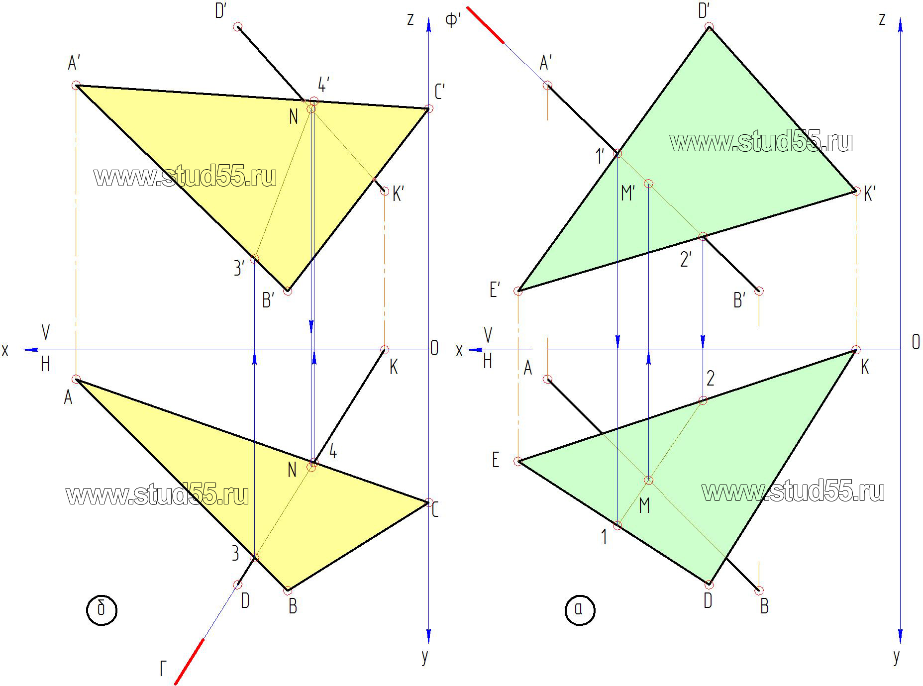
Fig.1.2
b) by connecting the projections of points 1 and 2, we will have the projection of the projecting plane F. Then the point of intersection of the line AB with the plane of the triangle DKE is determined (according to the rule) together with the intersection of the projection of the projecting plane 1-2 and the projection of the same name AB. Thus, we got a horizontal projection of the first point of intersection of the planes - M, along which we determine (project along communication lines) its frontal projection - M’ on a straight line A’ B’ (fig.1.2.a);
v) we find the second point in the same way. We conclude in the projecting plane G(G) side of the second triangle DK(DK) . We mark the points of intersection of the projecting plane with the sides of the first triangle ACandBC in a horizontal projection, getting projections of points 3 and 4. We project them onto the corresponding sides in the frontal plane, we get 3’ and 4'. Connecting them with a straight line, we have the projection of the projecting plane. Then the second point of intersection of the planes will be at the intersection of the line 3’-4’ with the side of a triangle D’ K’ , which was enclosed in a projecting plane. Thus, we got the frontal projection of the second intersection point - N’ , along the communication line we find the horizontal projection - N (fig.1.2.b).
G) by connecting the points MN(MN) and (M’ N’) on the horizontal and frontal planes, we have the desired line of intersection of the given planes.
4. With the help of competing points, we determine the visibility of the planes. Take a pair of competing points, for example, 1’=5’ in frontal projection. We project them onto the corresponding sides in the horizontal plane, we get 1 and 5. We see that the point 1 lying on the side DE has a large coordinate to the axis x than dot 5 lying on the side AV. Therefore, according to the rule of greater coordinate, the point 1 and the side of the triangle D'E’ in the frontal plane will be visible. Thus, the visibility of each side of the triangle in the horizontal and frontal planes is determined. Visible lines in the drawings are drawn with a solid contour line, and non-visible lines are drawn with a dashed line. Recall that at the points of intersection of the planes ( M— N andM’- N’ ) will change visibility.

Fig.1.3

RFig.1.4 .
The plot additionally shows the definition of visibility in the horizontal plane using competing points 3 and 6 on straight lines DK and AB.
5. Using the method of plane-parallel displacement, we determine the actual size of the plane of the triangle ABC, for what:
a) in the specified plane through a point C(C) conduct a frontal C— F(WITH-FandC’- F’) ;
b) on the free field of the drawing in a horizontal projection, we take (mark) an arbitrary point From 1, assuming that this is one of the vertices of the triangle (specifically, the vertex C). From it we restore the perpendicular to the frontal plane (through x-axis);

Fig.1.5
v) by plane-parallel movement we translate the horizontal projection of the triangle ABC, to a new position A 1 B 1 C 1 in such a way that in the frontal projection it takes a projecting position (transformed into a straight line). To do this: on the perpendicular from the point From 1, postpone the frontal projection of the horizontal C 1 — F 1 (length lCF) we get a point F 1 . A solution of a compass from a point F1 size F-A we make an arc serif, and from a point C 1 - notch size CA, then at the intersection of arc lines we get a point A 1 (second vertex of the triangle);
- similarly we get a point B 1 (from point C 1 make a notch with the size C— B(57mm), and from the point F 1 magnitude F— B(90mm). Note that with the correct solution, three points A 1 F’ 1 and B’ 1 must lie on one straight line (the side of the triangle A 1 — B 1 ) the other two sides WITH 1 — A 1 and C 1 — B 1 are obtained by connecting their vertices;
G) it follows from the rotation method that when moving or rotating a point in some projection plane - on the conjugate plane, the projection of this point should move in a straight line, in our particular case, along a straight parallel axis X. Then we draw from the points A’ B’ C’ From the frontal projection, these are straight lines (they are called the planes of rotation of the points), and from the frontal projections of the displaced points A 1 IN 1C 1 restore perpendiculars (connection lines) ( fig.1.6).

Fig.1.6
The intersection of these lines with the corresponding perpendiculars gives new positions of the frontal projection of the triangle ABC, specifically A’ 1 IN 1C’ 1 which should become a projecting (straight line) since the horizontal h 1 we drew perpendicular to the frontal projection plane ( fig.1.6);
5) then, to obtain the natural size of the triangle, it is enough to expand its frontal projection to parallelism with the horizontal plane. The reversal is carried out using a compass through a point A' 1, considering it as a center of rotation, we put a triangle A’ 1 IN 1C’ 1 parallel to axis X, we get A’ 2 IN 2C’ 2 . As mentioned above, when the point rotates, on the conjugate (now on the horizontal) projection, they move along straight lines parallel to the axis X. Omitting perpendiculars (link lines) from frontal projections of points A’ 2 IN 2C’ 2 crossing them with the corresponding lines we find the horizontal projection of the triangle ABC (A 2 IN 2C 2 ) real size ( fig.1.7).

Rice. 1.7
I have all ready-made solutions to problems with such coordinates, you can buy

Price 55 rubles, drawings on descriptive geometry from Frolov's book, you can easily download immediately after payment or I will send you an email. They are in a ZIP archive in various formats:
*.jpg – the usual color drawing of the drawing on a scale of 1 to 1 in a good resolution of 300 dpi;
*.cdw – format of the program Compass 12 and higher or version LT;
*.dwg and .dxf — AUTOCAD, nanoCAD program format;
Two planes in space can be parallel or intersecting, a special case of intersecting planes are mutually perpendicular planes.
The construction of the line of intersection of planes is one of the main tasks of descriptive geometry, which are of great practical importance. It belongs to the so-called positional tasks.
positional called tasks to determine the common elements of various conjugated geometric shapes. These include tasks for belonging geometric elements and to the intersection geometric objects, for example, the intersection of a line and a plane with a surface, the intersection of two surfaces and, in particular, the problem of the intersection of two planes.
The line of intersection of two planes is a straight line that simultaneously belongs to both intersecting planes. Therefore, to construct a line of intersection of planes, it is necessary to determine two points of this line or one point and the direction of the line of intersection.
Consider special case intersection of planes when one of them is projecting. On fig. 3.6 shows a plane in general position - given by the triangle ABC and horizontally projecting P. Two common points belonging to both planes are points D and E, which determine the line of intersection.
To determine these points, the points of intersection of the sides AB and BC with the projecting plane were found. The construction of points D and E both on a spatial drawing (Fig. 3.6, a) and on a diagram (Fig. 3.6, b) does not cause difficulties, because is based on the collective property of projecting traces of planes discussed above.
By connecting the projections of the same name of the points D and E, we obtain the projections of the line of intersection of the plane of the triangle ABC and the plane P. Thus, the horizontal projection D 1 E 1 of the line of intersection of the given planes coincides with the horizontal projection of the projecting plane P - with its horizontal trace.
Consider general case intersections when both planes are in common position. On fig. 3.7. two planes in general position are shown, given by a triangle and two parallel lines. To determine the two common points of the line of intersection of the planes, we draw two auxiliary (horizontal) level planes R and T. The auxiliary plane R intersects the given planes along two horizontals h and h 1, which in their intersection define point 1, common to the planes P and Q, so as they simultaneously belong to the auxiliary secant plane R. The second plane - mediator T also intersects each of the given planes along the horizontals h 2 and h 3, which are parallel to the first two horizontals. At the intersection of the contour lines, we get the second common point of 2 given planes. Combining on the diagram (Fig. 3.8, b) the projections of the same name of these points, we obtain the projections of the line of intersection of the planes.

On fig. 3.8 shows two planes defined by traces. The common points of the planes are the intersection points of M and N traces of the same name. Connecting the projections of the same name of these points with a straight line, I received the projections of the line of intersection of the planes.
If the intersection points of the traces of the same name are outside the drawing field (see example 5), and also in cases where the planes are specified not by traces, but by other geometric elements, then to determine the line of intersection of the planes, you should use auxiliary level planes- horizontal or frontal. It should be noted that when constructing the line of intersection of the planes specified by traces, the role of auxiliary secant planes is performed by the projection planes P 1 and P 2 .


On fig. 3.9 shows the case of the intersection of two planes, when the direction of the intersection line is known, since the plane P is the level plane (P||P 1). Therefore, it is sufficient to have only one point of intersection of traces and then draw a straight line through this point, based on the position of the planes and their traces. In our case, the line of intersection is the common horizontal of the NA planes P and T.
One of the fundamental problems of descriptive geometry is the problem of constructing a line of intersection of two planes in general position. The cases of specifying planes are different, but in any case, you will encounter a task in which it will be necessary to construct a line of intersection of two planes specified by triangles (or other flat geometric figures). I propose to consider the algorithm for solving such a problem now.
So, two planes given by triangles ABC and DEF are given. The method boils down to finding in turn two points of intersection of two edges of one triangle with the plane of another. By connecting these points we get the line of intersection of the two planes. The construction of the point of intersection of a straight line with a plane was considered in more detail in the previous lesson, I will only recall the mechanical actions:
We enclose the line AC in the front-projecting plane and transfer along the communication lines to the horizontal projection the points of intersection of this plane with the lines DE and DF - points 1 and 2
On the horizontal projection, let's connect the projections of points 1 and 2 and find the intersection point of the resulting line with the horizontal projection of the straight line that we enclosed in the front-projecting plane, in this case, with the straight line AC. We got point M.
We enclose the line BC in the front-projecting plane and transfer along the communication lines to the horizontal projection the points of intersection of this plane with the lines EF and DF - points 3 and 4
We connect their horizontal projections and get the point of intersection of this line with the line BC - point N.
By connecting the points M and N we get the line of intersection of the planes given by the triangles. In fact, the line of intersection has already been found. - It remains only to determine the visibility of the edges of the triangles. This is done by the method of competing points.

With the help of the most attentive visitors to the site, it was possible to find an inaccuracy in determining the visibility of the planes. Below is a drawing in which the visibility of the lines bounding the planes on the horizontal plane has been corrected

17. Method for replacing projection planes.
|
PROJECTION PLANE REPLACEMENT METHOD |
Changing the relative position of the object under study and the projection planes is achieved by replacing one of the planes P 1 or P 2 new planes P 4 (rice. 148 ). The new plane is always chosen perpendicular to the remaining projection plane.
To solve some problems, it may be necessary to double replace the projection planes (Fig. 149 ). A sequential transition from one system of projection planes to another must be carried out by following the following rule: the distance from the new point projection to the new axis must be equal to the distance from the replaced point projection to the replaced axis.
Task 1 : Determine the actual length of the segment AB straight line of general position (Fig. 148 ). From the property of parallel projection, it is known that a segment is projected onto a plane in full size if it is parallel to this plane.
Let's choose a new projection plane P 4 , parallel to the segment AB and perpendicular to the plane P 1 . By introducing a new plane, we pass from the system of planes P 1 P 2 into the system P 1 P 4 , and in the new system of planes the projection of the segment A 4 V 4 will be the natural length of the segment AB .
|
|

A straight line in space can be defined as a line of intersection of two non-parallel planes and, that is, as a set of points that satisfy a system of two linear equations
 (V.5)
(V.5)
The converse statement is also true: a system of two independent linear equations of the form (V.5) defines a straight line as a line of intersection of planes (if they are not parallel). The equations of system (V.5) are called general equation straight in space  .
.
ExampleV.12 . Compose the canonical equation of the straight line given by the general equations of the planes

Solution. To write the canonical equation of a line or, which is the same, the equation of a line passing through two given points, you need to find the coordinates of any two points on the line. They can be the points of intersection of a straight line with any two coordinate planes, for example Oyz and Oxz.
Point of intersection of a line with a plane Oyz has an abscissa  . Therefore, assuming in this system of equations
  , we get a system with two variables:

Her decision  ,
, together with
  defines a point
  desired straight line. Assuming in this system of equations
  , we get the system

whose solution  ,
, together with
  defines a point
  intersection of a line with a plane Oxz.
Now we write the equations of a straight line passing through the points  and
and  :
: or
or  , where
  will be the direction vector of this straight line.
ExampleV.13.
The straight line is given by the canonical equation  . Write the general equation for this line.
Solution. The canonical equation of a straight line can be written as a system of two independent equations:


We have obtained the general equation of a straight line, which is now given by the intersection of two planes, one of which  parallel to axis Oz
(
parallel to axis Oz
( ), and the other
  – axes OU
(
– axes OU
( ).
).
This line can be represented as a line of intersection of two other planes by writing its canonical equation as another pair of independent equations:


Comment . The same line can be given by different systems of two linear equations (that is, by the intersection of different planes, since countless planes can be drawn through one line), as well as by different canonical equations (depending on the choice of a point on the line and its direction vector) .
A non-zero vector parallel to a straight line, we will call it guide vector .
Let in three-dimensional space  given straight line l passing through the point
  , and its direction vector
  .
.
Any vector  , where
  , lying on a straight line, is collinear with the vector
  , so their coordinates are proportional, that is
 . (V.6)
This equation is called the canonical equation of the line. In the particular case when ﻉ is a plane, we obtain the equation of a straight line on a plane
 . (V.7)
ExampleV.14.
Find the equation of a straight line passing through two points  ,
, .
.
 ,
,
where  ,
, ,
, .
.
It is convenient to write equation (V.6) in parametric form. Since the coordinates of the direction vectors of the parallel lines are proportional, then, assuming
 ,
,

where t
- parameter,  .
.
Distance from point to line
Consider a two-dimensional Euclidean space ﻉ with a Cartesian coordinate system. Let the point  ﻉ and lﻉ. Find the distance from this point to the line. Let's put
  , and a straight line l is given by the equation
  (Fig. V.8).
Distance  , vector
  , where
  is the normal line vector l,
 and
and  are collinear, so their coordinates are proportional, i.e.
  , hence,
  ,
,
 .
.

From here  or multiplying these equations by A and B respectively, and adding them together, we find
  , hence
 .
.
 (V.8)
(V.8)
defines the distance from a point  to straight
  .
.
ExampleV.15.
Find the equation of a straight line passing through a point  perpendicular to the line l:
 and find the distance from
  to straight l.
From fig. V.8 we have  , and the normal vector is a straight line l
 . From the perpendicularity condition, we have
Because  , then
 . (V.9)
This is the equation of the line passing through the point  , perpendicular to the line
  .
.
Let we have the equation of the straight line (V.9) passing through the point  , perpendicular to the line l:
 . Find the distance from the point
  to straight l, using formula (V.8).
To find the desired distance, it is enough to find the equation of a straight line passing through two points  and point
  lying on the line at the base of the perpendicular. Let
  , then
Because  , and the vector
  , then
 . (V.11)
Since the point  lies on a straight line l, then we have another equality
  or
or

Let us bring the system to a form convenient for applying Cramer's method

Its solution looks like
 ,
,
 . (V.12)
Substituting (V.12) into (V.10), we obtain the original distance.
ExampleV.16.
A point is given in two-dimensional space  and direct
  . Find distance from point
  to a straight line; write the equation of a line passing through a point
  perpendicular to a given line and find the distance from the point
  to the base of the perpendicular to the original line.
By formula (V.8) we have
The equation of a straight line containing a perpendicular can be found as a straight line passing through two points  and
and  , using formula (V.11). Because
  , then, taking into account that
  , a
, a  , we have
 .
.
To find coordinates  we have a system taking into account the fact that the point
  lies on the original line

Hence,  ,
, , from here.
Consider a three-dimensional Euclidean space ﻉ. Let the point  ﻉ and plane ﻉ. Find the distance from this point
  to the plane given by the equation (Fig. V.9).

Similarly to the two-dimensional space, we have  and vector
  ah, from here
 . (V.13)
We write the equation of a straight line containing a perpendicular to the plane as the equation of a straight line passing through two points  and
and  lying in the plane :
 . (V.14)
To find the coordinates of a point  to any two equalities of formula (V.14) we add the equation
Solving the system of three equations (V.14), (V.15), we find  ,
, ,
, - point coordinates
  . Then the perpendicular equation can be written as
 .
.
To find the distance from a point  to the plane instead of formula (V.13) we use


