A voltage regulator for a car is a device whose function is to maintain voltage in the vehicle’s on-board network at within the established framework, regardless of the generator rotor speed, external temperature, load, etc.
Voltage regulator for cars
Performs this device and some additional functions: protection of the generator and its elements from overloads and operation in emergency modes, automatic activation of the alarm system for emergency operation of the generator or excitation winding circuit.
The voltage of the generator is influenced by three main factors: the speed of its rotor, magnetic flux, which is created by the current of the excitation winding, as well as the current strength that is supplied by the generator to the load.
The generator voltage increases with increasing speed, as well as with decreasing load. In addition, an increase in voltage causes an increase in current in the field winding.
The voltage regulator stabilizes the voltage by adjusting the excitation current. If the voltage increases and goes beyond the required limits, the regulator increases or decreases the excitation current, which leads to voltage stabilization.
The voltage regulator for a car is connected to the excitation winding of the generator, and voltage from the generator or battery is also supplied to it. Of course, regulators with an extended list of functions require more connections.
A voltage regulator for a car consists of several main elements:
(typography list_number_bullet_blue)1. Measuring element;||2. Comparison element;||3. Regulating element.(/typography)
A very sensitive and vulnerable part of the regulator is its input voltage divider. From it, voltage is supplied to the comparison element. IN in this case The reference value is the stabilization voltage of the zener diode.
If the voltage indicator is below the stabilization level, the zener diode does not pass current through itself. If the voltage exceeds the permissible limits, the zener diode begins to pass current through itself. On the zener diode itself, the voltage practically does not change.
The current passing through the zener diode activates the relay, which switches the excitation circuit so that the current in the excitation winding is adjusted in the required direction. Automotive voltage regulators perform discrete regulation. This is possible by turning on or off the excitation winding in the power circuit. This principle is inherent in transistor voltage regulators.
In vibration or contact-transistor regulators, the excitation winding is switched on in series with the winding of an additional resistor. It is worth noting that today only transistor voltage regulators are used for cars, and vibration and contact-transistor ones have already become a thing of history.
Voltage regulator for cars
The planned introduction of air conditioning based on Peltier elements is slowly moving forward. The next step after installing a 135 Amp generator was upgrading the voltage regulator. The main problem here is the operation of the air conditioner on the XX engine. The fact is that the generator pulley is three times smaller than the pulley crankshaft, at 1000 engine revolutions, the generator rotor will rotate at a speed of 3000 revolutions per minute, which, according to the current output table, will give 110 Amperes at 13.5 Volts:
In principle, when consuming 10 pellet elements, 60 Amps should be enough. However, I think so, these readings were taken when those same 13.5 Volts were applied to the rotor. And here we run into a standard voltage regulator, for which a voltage drop of 2 Volts is directly declared, that is, a maximum of 11.5 Volts will go to the rotor. The difference in rotor power will be 13.5 * 13.5 / 11.5 * 11.5 = 37%. That is, from 110 Amps only 70 will remain, of which 6 will go to the generator itself. And there are also regular consumers, that is, there will be little current left for the air conditioner. The 2-volt drop on the regulator is due to the use of a bipolar transistor in it as a switch.
Also, when upgrading, I wanted to add a function to turn off the generator when starting the engine. That is, normally when the starter is operating, the generator tries to generate, while consuming up to 6 amperes of current and braking the crankshaft. When the generator is turned off, we will get at least a 10% increase in the speed of rotation of the crankshaft by the starter. The main effect of this should be in winter, when the battery is operating at the limit of its capabilities.
So, when developing a voltage regulator, the following factors must be taken into account:
- Wide operating temperature range from -40 to +80,
- Resistant to voltage surges up to 60-80 Volts,
- Weather resistance,
- Vibration resistance
- Possibility of switching off when starting the engine,
- Low voltage drop,
- No mechanical elements.
One of the alternative voltage regulator circuits is the following:

However, it has the following disadvantages:
- The temperature range of LM393 is only from 0 to +70,
- LM393 can withstand a maximum of 30 Volts of power,
- The IRF 3205 shutter is designed for a maximum of 10 Volts, there is no protection on the circuit,
- irf 3205 can withstand a maximum of 30 Volts at the drain-source terminals (the bipolar transistor in the original is designed for 80 Volts),
- the field-effect transistor is controlled without a key - this will lead to its heating,
- There is no possibility of switching off when starting the engine,
- The diagram contains trim resistor- I don’t recommend using anything tuning in the car,
- The relay is potentially a weak link.
The original voltage regulator circuit looks like this:

The principle of operation is primitive - when the set voltage is exceeded, the rotor is turned off, after the voltage is reduced, the rotor is reconnected. The principle of operation is the same as that of a carburetor float chamber, or a toilet cistern. I was interested in the elements for discharging the energy of the residual induction of the rotor - inductor 7, diode 12 and capacitor 11. For this I bought a new voltage regulator, I wanted to use its housing for company:

As you understand, “effective” managers sneaked into the plant long ago and threw out these unnecessary elements, leaving only the protective diode:

At the same time, the board itself was made by us - high-quality soldering is visible (the Chinese don’t do that) and is varnished. Subsequently, I opened my original voltage regulator from 1996 and saw those same protective elements:

Please note that the bolt through which the mass flows is also soldered; in the remake, the terminal is simply tightened. Another note about the remake is the thin wires going to the connector. The maximum current on the rotor can be up to 6 Amperes, this implies a wire with a cross-section of 2 square meters. mm., or 1.5 mm in diameter.
As a result, I developed my own scheme:

I used the PWM step-down stabilizer lm2576-adj as a basis; it once proved itself well in LED PTFs. The TC4420EPA microcircuit is the key that ensures instant switching of the field-effect transistor, which is why it does not heat up in vain. The transistor was originally CEB4060AL, I will write about it in more detail later. All parts are designed for the range from -40 to +80, most of the parts were purchased from the Chip NN store. Purpose of parts:
- diode D1 - I don’t know why, it should be in the regulator with a voltage of 400 Volts, a current of 1 Ampere.
- resistor p3, capacitor c1 and two zener diodes vd1 and vd2 protect the control microcircuits and the gate of the field-effect transistor from voltage surges. If 16 Volts are exceeded, the zener diodes will open and the excess voltage will be dissipated by resistor p3. Resistor power 2 Watt, zener diodes 1 Watt each. A capacitor of several hundred microfarads for a voltage of 50 Volts
- Resistors p1 and p2 are a voltage divider along which the stabilizer is oriented. You'll have to choose according to location.
- dd1 - PWM stabilizer changes the duty cycle of the pulses on the field-effect transistor and, accordingly, on the rotor. It has a tricky pin 5, when voltage is applied to which the PWM is turned off, we will connect it to the starter relay. P5 is needed for the correct operation of the stabilizer; this pin is either an open collector or an emitter.
- resistor p4 is guaranteed to remove voltage from the shutdown input, that is, the microcircuit will not freeze in an intermediate state, diode d3 is needed to discharge the voltage from the holding winding of the starter relay. Diode d2 limits the control voltage.
- dd2 chip control key field effect transistor, ensures its instant disabling/enabling. This reduces the heating of the key transistor in intermediate states and accordingly increases the efficiency of the circuit. I installed capacitor c2 according to the datasheet’s recommendation.
- resistor p6 is guaranteed to shut down the transistor in unclear situations.
- There are two diodes d4 and d5. Since I used UF4007, and they can withstand up to 1 Ampere, the standard circuit has a 1.5 Ampere diode. They discharge the energy stored in the rotor when the circuit is opened.
- inductance l1 and capacitor c3 ensure smooth discharge of the rotor without a large jump in the circuit.
I cut out the boards. It's more comfortable for me. Here's the board below:

And from above:

All low power SMD resistors and capacitor:

The field-effect transistor initially used CEB4060AL - due to the fact that it holds up to 20 Volts at the gate, and up to 60 Volts at the source relative to the drain. However, when testing with a current of 6 Amperes - a 55 Watt PTF light bulb, the transistor encountered heating. Without the driver, it could have been blamed on the slow opening/closing of the transistor, but there was a driver. I took up the curculator. The CEB4060AL channel resistance is 80 milliOhms. Yes, a lot - but this is the price to pay for the ability to hold high voltage. So the dissipation power is 6 Amps * 6 Amps * 0.08 Ohm = 2.9 Watts. Looks like it's true. In general, a heat dissipation of 3 Watts could be tolerated, if not for one thing. Under the hood it can easily reach +80, and in such conditions the additional heat generation will simply kill the circuit.
For correct operation of a car generator, voltage regulation is necessary. Thanks to the device, the potential is maintained in the operating range.
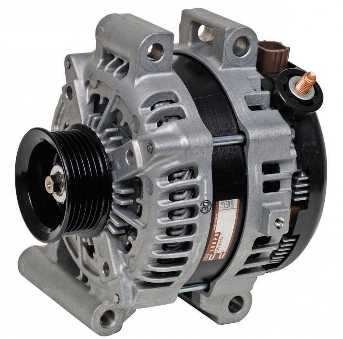
General view of a car generator
It is important to know about the structure, operating principle, diagnostics, repair and replacement of the voltage regulator in a car. This will allow you to avoid a number of negative situations on the road, such as failure to start the engine, burning out the car wiring.
Generator structure
Regardless of the make and model of the car, the type of car generator, a voltage regulator is always included in the design, allowing it to maintain operation regardless of the rotor speed. The adjustment is carried out by changing the strength of the electric current on the rotor winding.
Generator components (diagram):
- The stator (housing) is the stationary part of a car generator.
- There are three windings, they are connected into one by a star, which generates a three-phase alternating voltage.
- A rotor on the blades of which a magnetic field and EMF are formed.
- Three-phase rectifier - semiconductor diodes that convert voltage. One side of the diodes is conductive, the other has an insulated surface.
- Automatic voltage regulation device.

Car generator rotor
Three windings can significantly reduce ripple due to phase overlap.
Generator operating principle
When the rotor moves, an EMF occurs at the output of the car generator, which is directly connected to the battery. With the help of adjustment, it is transmitted to the stator field winding. As the rotor speed increases, the voltage begins to change.
Voltage on the winding is always present.
To stabilize the voltage value, a voltage regulator relay is installed, where processing and comparison (in the analytical unit) of the input signal takes place. If there is a deviation from the norm, the control unit sends a signal to the actuator, where the current decreases. After this, the voltage at the output of the car generator stabilizes. If the current value is too low, the regulator increases the output voltage.
The principle of operation of the voltage regulator
To increase operational reliability, regulators are made according to simplified circuits. Includes several devices: signal comparison, control element, master and special sensors.
The finished circuit consists of two main elements:
- Regulator. A device that allows you to adjust and control voltage. It is manufactured in two versions – analog (mechanical) and digital (electronic).
- Graphite brushes that connect to semiconductor elements. Designed to communicate voltage to the rotor of a car generator.

Graphite brushes transmit voltage to the car's generator rotor
Modern devices have a microprocessor base.
Two-level regulation scheme
It consists of three main elements: a generator, a battery, and a rectifier. There is a magnet inside the device, the winding of which is connected to the controller. Metal springs are used as setting devices, and movable levers are used as comparing devices. The contact group is used as a measuring device, and a constant resistance as a control device.

Two-level voltage regulator
Operating principle of a two-level regulator
If tension occurs and electromagnetic field signals are compared. A spring is used as a comparison device, which acts on the lever arm. The magnetic field acts on the lever in several directions (closes, opens, remains unchanged), after which the regulator circuit operates depending on the voltage value.
When the signal goes beyond the operating range, the contacts open.
A constant voltage is connected to the circuit.
In this case, less current is supplied to the winding and the voltage is stabilized. If the contacts initially short, indicating low voltage, the current increases and the generator continues to operate normally.
Disadvantages of mechanical models:
- rapid wear of parts;
- use of electromagnetic relays.
Electronic regulators
They work identically to analog models, except that the mechanical elements are replaced with digital sensors. Instead of electromagnetic classical relays, thyristors, triacs, transistors, etc. are used. The sensitive element is a system of constant resistors installed on a voltage divider.

Electronic regulator circuit
The principle of operation is as follows: when voltage is applied to the thyristors, the output signals are compared. Executive agency depending on the received data, it closes or opens, if necessary, including additional resistance in the circuit.
Advantages of electronic models:
- high adjustment accuracy;
- the regulator is installed in a single unit with brushes, which saves space and simplifies diagnostics, repair and replacement of equipment;
- increased reliability and durability;
- more fine tuning device;
- Semiconductor diodes are used as rectifiers, which ensure stability of the output voltage;
- the driving element is made in the form of a zener diode.
For new car models, it is advisable to use more advanced control systems due to a more complex technical device.
Removing the voltage regulator
In order to remove the regulator from the back cover of the car generator, you need a screwdriver (phillips or flat-head). The generator itself and the belt do not need to be removed.
The structure can only be removed after disconnecting the battery. Next, you need to disconnect the wire from the car generator by unscrewing the mounting bolts.
The main causes of autogenerator malfunctions:
- erasing carbon brushes;
- breakdown of insulation of semiconductor elements.
Checking the functionality of the regulator
On almost all car models, the regulator relay is diagnosed in the same way. To carry out diagnostics, you need a constant voltage source (battery, batteries), a 12 V lamp or a voltmeter.
The minus contact is connected to the device plate, the plus contact is connected to the regulator relay connector.
After removing the regulator from the body, it is necessary to check the functionality of the brushes. If they are less than 5mm in length, then the brush assembly must be replaced.
An incandescent lamp must be included in the circuit between a pair of brushes:
- the extinguishing of the light bulb as the voltage increases indicates the serviceability of the device;
- Constant lighting of the light when changing parameters indicates a malfunction of the voltage regulator.
Soldering new brushes will not bring results, because... the reliability of the design will be significantly reduced. It is unacceptable to use LED products for testing, because Carrying out diagnostics according to this scheme will not give real results.
Test without stress relief
It consists of measuring the on-board voltage in the car. The presence of surges in the network is also determined by the blinking of the lamps during the trip. To check, you will need a multimeter (or a regular incandescent lamp). A multimeter allows you to get more accurate results.
Procedure:
- Start the engine, turn on the headlights.
- Connect the measuring device to the battery.
- The operating voltage ranges from 12 to 14.8 V. If the voltage regulator goes beyond this range, it is considered faulty.
Testing under voltage does not determine the condition of the brush assembly. Exceeding the operating voltage parameters may be associated with weakening or oxidation of contacts.
The operation of control systems in cars is being improved. For modern cars there is no point in using two-level regulation. More advanced systems have 2 or more additional resistances. In new models, instead of the traditional additional resistance, the principle of increasing the frequency of operation of the electronic key is used.
Along with the classical ones, automatic servo control systems are used, in which there is no electromagnetic relay.
The most common method is a three-level frequency modulation control circuit to control logic elements.
Three-level regulation scheme
The quality of battery charging depends on the efficiency of the voltage regulator. When not fully charged, the battery loses capacity at a high rate, and subsequently it becomes impossible to start the engine.

Three-level voltage regulator
Two-level models have a big drawback - the spread of the output voltage. Therefore, to increase the stability of the system, a three-level adjustment system is used, which includes a toggle switch (changes the system parameters).
The use of this type of model allows for more accurate diagnostics and control of the potential at the output of the generator, which is important for new models of the mid-price level, where manufacturers do not always use high-quality mechanisms.
The most relevant application of this system is in winter time years in regions with cold climates, when from low temperatures The battery capacity is greatly reduced. Mechanical regulators have been replaced by non-contact three-level, more advanced ones.
The circuit and principle of operation are similar to two-level models, except that the voltage first goes to the information processing unit. If there is a deviation from the operating value, a sound signal (mismatch) is given. After this, the electric current supplied to the winding changes to the operating value.
Installation principle
It is allowed to install three-level models in any car yourself, provided you know the connection diagram:
- It is necessary to disconnect the brush assembly by unscrewing the bolts.
- Install the semiconductor assembly on the car body, making the necessary fastenings.
- The semiconductor assembly is installed first on an aluminum radiator, because requires efficient cooling and is then secured to the case.
If there is no cooling system, regulation will not occur correctly.
- After installing the two units, it is necessary to ensure an electrical connection between them with wires, ensuring high-quality insulation of the housings.
Surfaces must be covered with insulating material to prevent short circuits to the housing. A switch should be provided for switching semiconductors.
To install the structure, a housing is required. Usually plastic or aluminum is used, which has greater heat transfer, i.e. cooling will occur more efficiently.
Video. Generator in a car
The voltage regulator in the car circuit occupies one of the key places. It is necessary to constantly monitor the condition of the device, carry out scheduled inspections in a timely manner, and clean the contacts (to prevent malfunctions). Because The part is located on the lower side of the engine compartment, not protected from dust and moisture; regularly clean the surfaces from dirt.
If there are external defects or damage, you should not use such devices, because in this case, a rapid discharge of the battery or complete failure of the car generator, as well as the electrical part of the car (due to a sharp increase in voltage in the on-board network), is possible.
The generator voltage regulator relay is an integral part of the electrical system of any car. With its help, voltage is maintained in certain range values. In this article you will learn about what designs of regulators exist on this moment, including mechanisms that have not been used for a long time will be considered.
Basic automatic control processes
It doesn't matter what type of generator set is used in the car. In any case, it has a regulator in its design. The automatic voltage regulation system allows you to maintain a certain parameter value, regardless of the frequency at which the generator rotor rotates. The figure shows the generator voltage regulator relay, its diagram and appearance.
Analyzing physical basis, using which the generator set operates, we can come to the conclusion that the output voltage increases if the rotor speed becomes higher. It can also be concluded that voltage regulation is carried out by reducing the current supplied to the rotor winding as the rotation speed increases.

What is a generator
Any car generator consists of several parts:
1. A rotor with an excitation winding, around which an electromagnetic field is created during operation.
2. A stator with three windings connected in a star configuration (alternating voltage is removed from them in the range from 12 to 30 Volts).
3. In addition, the design contains a three-phase rectifier consisting of six semiconductor diodes. It is worth noting that the VAZ 2107 generator voltage relay-regulator in the injection system is the same.
But the generator will not be able to operate without a voltage regulation device. The reason for this is the voltage change over a very wide range. Therefore, it is necessary to use an automatic control system. It consists of a comparison device, control, executive, master and special sensor. The main element is the regulatory body. It can be either electrical or mechanical.

Generator operation
When the rotor begins to rotate, some voltage appears at the generator output. And it is supplied to the excitation winding through a control element. It is also worth noting that the generator set output is connected directly to the battery. Therefore, voltage is constantly present on the excitation winding. When the rotor speed increases, the voltage at the generator set output begins to change. A voltage regulator relay from a Valeo generator or any other manufacturer is connected to the generator output.
In this case, the sensor detects the change, sends a signal to a comparing device, which analyzes it, comparing it with a given parameter. Next, the signal goes to the control device, from which it is supplied to the Regulating body, which is able to reduce the value of the current that flows to the rotor winding. As a result, the voltage at the generator set output is reduced. In a similar way, the mentioned parameter is increased in the event of a decrease in rotor speed.

Two-level regulators
A two-level automatic control system consists of a generator, a rectifier element, and a battery. It is based electric magnet, its winding is connected to the sensor. The driving devices in these types of mechanisms are very simple. These are ordinary springs. A small lever is used as a comparison device. It is mobile and makes switching. The actuator is the contact group. The control element is a constant resistance. Such a generator voltage regulator relay, the diagram of which is given in the article, is very often used in technology, although it is morally outdated.

Operation of a two-level regulator
When the generator operates, a voltage appears at the output, which is supplied to the winding of the electromagnetic relay. In this case, a magnetic field arises, with its help the lever arm is attracted. The latter is acted upon by a spring, which is used as a comparing device. If the voltage becomes higher than expected, the contacts of the electromagnetic relay open. In this case, a constant resistance is included in the circuit. Less current is supplied to the field winding. The voltage regulator relay for the VAZ 21099 generator and other domestic and imported cars operates on a similar principle. If the voltage at the output decreases, then the contacts are closed, and the current strength changes upward.
Electronic regulator
Two-level mechanical voltage regulators have a big drawback - excessive wear of the elements. For this reason, instead of an electromagnetic relay, semiconductor elements operating in key mode began to be used. The operating principle is similar, only the mechanical elements are replaced by electronic ones. The sensitive element is made of fixed resistors. A zener diode is used as a driving device.
The modern relay-voltage regulator of the VAZ 21099 generator is a more advanced device, reliable and durable. The executive part of the control device operates on transistors. As the voltage at the generator output changes, the electronic switch closes or opens the circuit, and additional resistance is connected if necessary. It is worth noting that two-level regulators are imperfect devices. Instead, it is better to use more modern developments.

Three-level regulation system
The quality of regulation of such structures is much higher than that of those previously discussed. Previously, mechanical designs were used, but today non-contact devices are more common. All elements used in this system are the same as those discussed above. But the operating principle is slightly different. First, voltage is applied through a divider to a special circuit in which information is processed. It is possible to install such a generator voltage regulator relay (Ford Sierra can also be equipped with similar equipment) on any car if you know the device and connection diagram.
Here the actual value is compared with the minimum and maximum. If the voltage deviates from the value that is set, then a certain signal appears. It is called a mismatch signal. It is used to regulate the current flowing to the excitation winding. The difference from a two-level system is that there are several additional resistances.

Modern voltage regulation systems
If the relay-regulator of the voltage of the Chinese scooter generator is two-level, then expensive cars more advanced devices are used. Multilevel control systems can contain 3, 4, 5 or more additional resistances. There are also automatic control tracking systems. In some designs, you can refuse to use additional resistances.
Instead, the frequency of operation of the electronic key increases. Use schemes with electromagnetic relay is simply impossible in servo control systems. One of latest developments- This multi-level system control that uses frequency modulation. In such designs, additional resistances are required, which are used to control logic elements.
How to remove the relay regulator
Removing the generator voltage regulator relay (Lanos or domestic “Nine” is not important) is quite simple. It is worth noting that when replacing the voltage regulator, you only need one tool - a flat-head or Phillips screwdriver. There is no need to remove the generator or the belt and its drive. Most of the devices are located on the back cover of the generator, and are combined into a single unit with a brush mechanism. The most common breakdowns occur in several cases.
Firstly, when completely erasing the graphite brushes. Secondly, in case of breakdown of a semiconductor element. How to check the regulator will be discussed below. When removing, you will need to disconnect the battery. Disconnect the wire that connects the voltage regulator to the generator output. By unscrewing both mounting bolts, you can pull out the device body. But the voltage regulator relay has an outdated design - it is mounted in the engine compartment, separately from the brush assembly.

Device check
The relay-regulator of the voltage of the VAZ 2106 generator, "kopecks", and foreign cars is checked equally. As soon as you remove, look at the brushes - they should be more than 5 millimeters long. If this parameter is different, the device must be replaced. To carry out diagnostics, you will need a constant voltage source. It would be desirable to be able to change the output characteristic. You can use a battery and a couple of AA batteries as a power source. You also need a lamp, it must run on 12 Volts. You can use a voltmeter instead. Connect the plus from the power supply to the voltage regulator connector.

Accordingly, connect the negative contact to the common plate of the device. Connect a light bulb or voltmeter to the brushes. In this state, voltage should be present between the brushes if 12-13 Volts are supplied to the input. But if you supply more than 15 Volts to the input, there should be no voltage between the brushes. This is a sign that the device is working properly. And it doesn’t matter at all whether the voltage regulator relay of the VAZ 2107 generator or another car is diagnosed. If the control lamp lights up at any voltage value or does not light up at all, it means that there is a malfunction of the unit.

conclusions
In the electrical system of a car, the relay-voltage regulator of the Bosch generator (as, indeed, of any other company) plays a very important role. big role. Monitor its condition as often as possible and check for damage and defects. Cases of failure of such a device are not uncommon. In this case, in the best case, the battery will be discharged. And in the worst case, the supply voltage in the on-board network may increase. This will lead to the failure of most electricity consumers. In addition, the generator itself may fail. And its repair will cost a tidy sum, and considering that the battery will fail very quickly, the costs will be astronomical. It is also worth noting that the Bosch generator voltage regulator relay is one of the leaders in sales. It has high reliability and durability, and its characteristics are as stable as possible.
If problems arise with the car battery, you should pay attention to the operation of the voltage regulator relay. What problems can there be with the battery? It has stopped charging from the generator and is quickly discharged or, conversely, recharged. In this case, it is necessary to check the generator voltage relay.
The voltage regulator relay should turn off at a voltage of 14.2-14.5 Volts.
Why do you need a voltage regulator in a car?
This small, simple device performs important function- voltage regulation. That is, if the voltage is greater than set, the regulator should reduce it, and if the voltage is less than set, the regulator should raise it.
What voltage does the generator relay regulate?
The running engine ensures the operation of the generator, which generates and transmits voltage electric current battery.
If the voltage regulator does not work correctly, the car battery quickly drains its life. The regulator is sometimes called a pill or a chocolate bar.
Types and types of regulator relays
Depending on the type of relay, the method for determining performance also depends. Regulators are classified into 2 types:
- combined;
- separate.
Combined relays - this means that the relay itself with the brush assembly is located in the generator housing.
Separate relays - this means that the relay is located outside the generator housing and is mounted on the car body. You've probably seen a small black device attached to the fender of the car, wires go to it from the generator, and from it to the battery.
A distinctive feature of regulators from other devices is that the relays consist of a non-separable housing. During assembly, the body is glued with sealant or special resin. There is no point in disassembling and repairing it, since such electrical devices are inexpensive.
Signs of trouble
If the voltage is low, the battery will not be able to charge. Thus, the battery will quickly run out.
If, after the relay-regulator, the voltage goes to the battery at a high level (higher than set), the electrolyte will begin to boil and evaporate. At the same time, the battery appears white coating.
What signs of a breakdown of the car generator voltage regulator may be:
- After turning the ignition key, the warning lamp does not light up.
- After the engine starts, the battery indicator does not go out on the instrument panel.
- IN dark time During the day you can observe how the light becomes brighter and dimmer.
- The car's internal combustion engine does not start the first time.
- If the engine speed exceeds 2000, then all the dashboard lights may turn off.
- Loss of engine power.
- Battery boiling.
Causes of relay malfunction
The reasons include the following observations:
- Short circuit (SC) on any line of automotive electrical wiring.
- Diodes are broken. The rectifier bridge has closed.
- The battery terminals are not connected correctly.
- Water got inside the relay.
- Mechanical damage to the housing.
- Brush wear.
- The relay resource has expired.
How to quickly and easily check the voltage regulator
Take a multimeter or voltmeter and measure the voltage at the battery terminals. The check is done in the following order:
- Put the device in voltage measurement mode at up to 20 V.
- Start the internal combustion engine.
- At idle speed, measure the voltage at the battery terminals. In XX mode, engine speed is from 1000 to 1500 rpm. If the generator and voltage regulator are working properly, then the voltmeter should show a voltage of 13.4 to 14 Volts.
- Raise engine speed to 2000-2500 rpm. Now the voltage value with the generator and relay working properly, the multimeter (voltmeter, tester) should show a voltage from 13.6 to 14.2 V.
- Next, step on the gas and increase the engine speed to 3500 rpm. The voltage of working devices should be no more than 14.5 Volts.
The minimum permissible voltage that a working generator and voltage regulator should produce is 12 Volts. And the maximum is 14.5 Volts. If the device shows a voltage value less than 12 V or more than 14.5 V, then the voltage regulator must be changed.
In new cars, mainly the relay is combined with a generator. This helps avoid pulling separate wires and saves space.
How to check a combined relay
For example, consider the regulator of a VAZ 2110 car. To check whether the relay is working, you need to assemble a circuit such as in the figure.
Relay regulator VAZ 2110 - 37.3701:
- 1 - battery;
- 2 - ground terminal of the voltage regulator;
- 3 - voltage regulator;
- 4 – terminal “Ш” of the regulator;
- 5 - terminal “B” of the regulator;
- 6 - control lamp;
- 7 - terminal “B” of the voltage regulator.
When assembling such a circuit with a standard voltage of 12.7 Volts, the light bulb should simply glow.
If the regulator voltage is raised to 14-14.5 Volts, the light bulb should go out. If the light does not go out with this high voltage, then the regulator is faulty.
Checking the VAZ 2107 regulator
Until 1996, classic VAZ 2107 cars with a cipher generator 37.3701 were equipped with an old-style voltage regulator (17.3702). If such a relay is installed, then it should be checked as on the top ten (discussed above).
After 1996, they began to install a new generator of the G-222 brand (there is an integrated regulator RN Ya112V (B1).
Checking the regulator separately
 Generator regulator G-222:
- 1 - battery;
- 2 - voltage regulator;
- 3 - control lamp.
To check, you need to assemble the circuit shown in the figure. At a normal operating voltage of 12 V, the light bulb should just glow. If the voltage reaches 14.5 Volts, then the light should go out, and when it drops, it should light up again.
Checking relay type 591.3702-01
Relay test diagram: 
Such old relay models are sometimes installed on the classic VAZ 2101-VAZ 2107, on GAZ, Volga, Moskvich cars.
The relay is mounted on the body. It is checked according to the same scheme as the previous ones. But, you need to know the contact markings:
- “67” is the minus (-) contact.
- "15" is a plus.
The verification process is the same. At normal voltage, 12 Volts and up to 14 V, the light should light. If lower or higher, the light should go out.
PP-380
The PP-380 brand regulator was installed on VAZ 2101 and VAZ 2102 cars. Adjustable voltage at regulator temperature and environment(50±3)° C, V:
- at the first stage no more than 0.7
- at the second stage 14.2 ± 0.3
- Resistance between plug “15” and ground, Ohm 17.7 ± 2
- Resistance between plug “15” and plug “67” with open contacts, Ohm 5.65 ± 0.3
- Air gap between armature and core, mm 1.4 ± 0.07
- Distance between second stage contacts, mm 0.45 ± 0.1.
Testing a three-level relay
 As the name suggests, such relays have three voltage levels. This is a more advanced option. The voltage levels at which the battery will be disconnected from the voltage regulator can be set manually, for example: 13.7 V, 14.2 V, 14.7 V.
How to check the generator
To check functionality, you need to:
- Disconnect the wires going to terminals 67 and 15 of the regulator.
- Connect a light bulb to the wires. Bypassing the relay.
- Disconnect the positive terminal of the battery.
If the car does not stall, then the generator is working.
How to increase relay life
- Check the tension of the generator belt.
- Avoid excessive contamination of the generator.
- Check contacts.
- Inspect the battery. If there is a white coating on the battery case, it means that the voltage from the relay is greater than expected and the electrolyte is boiling.
Video
Useful video for auto electricians.
How the generator and voltage relay work.


