AutoCAD is a universal graphic system designed for designing clothes, machines, cars, houses, etc. AutoCAD can be launched from the shortcut on the desktop or from the Windows XP menu by choosing the AutoCAD program. The tutorial describes the program version AutoCAD2007.
The graphical user interface of AutoCAD is fully compliant with the standards used in Windows applications. Interaction with the AutoCAD program is provided by commands entered from the keyboard or selected from various menus and toolbars. After installing AutoCAD2007 and
the first launch, the dialog box shown in Fig.1.1 may appear. If choose from
In the list of workspace "3D modeling", the main window of AutoCAD2007 will have the form shown in Fig. 1.2, and if you select "Classic AutoCAD", the appearance of the main window will be somewhat different (Fig. 1.3).
The main functional areas are: working graphic area, directly in which the drawing is created; system menu and toolbars; command line; status bar.
Commands are essential elements of the AutoCAD graphical interface. All changes in the system occur as a result of the execution of a particular command. Introducing
the command you tell the system what action to take; reac-
speaks to commands and displays its messages (hints) in the command line. Posts
Figure 1.1 AutoCAD 2007 Dialog Box
are designed to inform the user about the status of the current operation, or offer to select possible options for further actions. To call commands in AutoCAD, there are the following tools: system menu AutoCAD; context menus; toolbars; command line.
After calling the command, the system displays either a prompt on the command line, or
dialog window. Many teams offer to select options for further actions (options); in tooltips, they are displayed in square brackets. For selection
option, just enter part of it.
Using the system menu
File(File) is a menu for opening and saving new and existing drawings, printing, exporting files to other formats, performing some other common file operations, and also logging off the system.
Edit(Edit) - menu for editing parts of the working area.
View(View) -menu, which contains commands for controlling the screen, panning, switching paper space and model space modes, setting a point
vision, removal of invisible lines, shading, toning, control of display parameters.
1 2 3 4 5 6 7 8

9 10 11 12 13 14 15 16 17 18 19 20
Fig.1.2. The main window of AutoCAD2007 - workspace "3D modeling"
1-button system menu; 2-line header; 3-line menu; 4-standard toolbar; 5-layers toolbar; 6-toolbar styles; 7-toolbar property of objects; 8-buttons for window control; 9-toolbar drawing (drawing); 10- working graphic area; 11- command line; 12- status bar; 13-user coordinate system (UCS) icon; 14-axis X; 15-axis Y; 16-major axes; 17-minor axes; 18-crosshair cursor; 19-horizontal and vertical scroll bars; 20-toolbar edit (edit)
1 2 3 4 5 6 7 89

10 11 12 13 14 15 16 17 19 20
Fig.1.3. The main window of AutoCAD2007 - workspace "ClassicAutoCAD"
1-button system menu; 2-line header; 3-line menu; 4-standard toolbar; 5-toolbar workspace; 6- layers toolbar; 7-toolbar styles; 8-toolbar property of objects; 9-buttons for window control; 10-toolbar drawing (drawing); 11- character of the user coordinate system (UCS); 12-tab “Model”; 13-tab “Sheet”; 14-working graphics area; 15- command line; 16- status bar; 17-cursor; 19-horizontal and vertical scroll bars; 20-toolbar edit (edit)
Merge- a menu containing commands for inserting blocks, xrefs and objects from other applications.
Format(Format) - this menu provides work with layers, color, line type and thickness, control of text style, dimensions, multiline style, setting borders
drawing and units of measure.
Service(Tools) - the menu contains system controls, includes setting drawing and binding parameters using dialog boxes, provides work with
custom coordinate system.
Drawing- the menu contains commands for drawing graphic primitives on the screen.
Dimensions (edit)(Dimension) - contains commands for setting dimensions in the current drawing.
The change or editing (Modify) - includes commands for making changes to the current drawing.
Menu Express- fast execution of commands.
Menu Window- contains tools for managing windows when working in multi-window mode.
Help(Help) - contains help.
You can customize your workspace to create a drawing environment that displays only the toolbars, menus, and dockable windows you select. A workspace refers to a family of user interface elements, including content, properties, display states, and a folder.
Setting interface parameters
The application interface is customizable according to the nature of the work. Access to various settings is provided by the context menu (Fig. 1.4) and the "Settings" dialog box (Fig. 1.5). In the "Settings" dialog box, you can
changing various parameters of windows and working environment. For the context menu to appear, right-click the mouse in the working graphics area. Another option for opening the Options window is to use the Tools - Options menu bar. You can also open the window by right-clicking in the command window and choosing Options. The Options dialog box consists of the following tabs:
Files, Figure 1.6.
Screen, see Fig. 1.5.
Opening / Saving, Fig. 1.7.
Print / Publish, Figure 1.8.
System, Figure 1.9.
Custom, Figure 1.10.

Figure 1.4. Context menu

Fig.1.5. Dialog box "Settings", tab Display
Constructions, fig. 1.11.
3D modeling, fig. 1.12.
Selection, Figure 1.13.
Profiles, Figure 1.14.

Fig.1.6. Dialog box "Settings", tab Files

Fig. 1.7. "Options" dialog box, Open / Save tab

Figure 1.8 The Options Dialog Box, Print / Publish Tab

Fig.1.9. Dialog box "Settings", tab System

Figure 1.10. Settings Dialog Box, Custom Tab

Fig. 1.11. "Options" dialog box, Build tab

Fig. 1.12. Dialog box "Settings", tab 3D modeling

Figure 1.13. The Settings Dialog Box, Selection Tab

Figure 1.14. Dialog box "Settings", tab Profiles
Some elements of the workspace, such as the appearance and position of panels and palettes, are set and saved using the Customize User Interface dialog box, invoked using the Tools - Customization - Interface menu, or using the Context Menu, which can be called by right-clicking on any panel and select "Adaptation" (Fig. 1.15).

Figure 1.15. Customize User Interface Dialog Box
With the AutoCAD customization tools, you can customize the drawing environment to suit your needs. Customization options are available for creating and modifying custom content, such as the Customize User Interface (CUI) file format and the Customize User Interface dialog box. The XML-based CUI file replaces menu files that were used in releases prior to AutoCAD 2006. Instead of using a text editor to customize menu files (MNU and MNS), the user interface can be customized using AutoCAD. You can do the following.
Add or modify toolbars and menus (including context menus, image menus, tablet menus).
Create or modify workspaces.
Assign commands to various elements of the user interface.
Create or modify macros.
Set DIESEL strings.
Create or modify aliases.
Create tooltips
Display descriptive text on the status bar.
Customizing the user interface
To efficiently perform tasks when working in the program, use menus, toolbars, keyboard shortcuts for quick selection of commands and other interface elements. You can speed up your work by customizing the following basic elements of your workspace.
User Interface Customization Dialog Box Overview With the AutoCAD customization tools, you can customize the drawing environment to suit your needs.
Working with configuration files Customization files (CUIs) are used to store commands, user interface elements, and links to partial CUI and AutoLISP files. CUI files can be master, partial, or corporate. The purpose of the CUI file determines the order in which it is loaded. User interface elements can be transferred between CUI files to facilitate the migration process.
Configuration commands Commands can be easily created, edited and reused. On the Customize tab of the Customize User Interface Editor
displays the main list of commands loaded in the program. Commands from this list can be added to toolbars, menus, and other user interface elements.
Creating macros A menu macro describes the action that will be performed when an interface element is selected. A macro implements a build task, for which the user would need to perform several operations. A macro can contain commands, special characters, and DIESEL (Direct Interpretively Evaluated String Expression Language) or AutoLISP code.
Customizing Toolbars You can customize the toolbar to improve drawing efficiency or workspace utilization, which is as simple as placing or resizing in the drawing area. You can also create or edit toolbars and their submenus by adding controls or commands and creating or editing toolbar buttons.
Create drop-down and shortcut menus A drop-down menu below the menu bar will display a list. Shortcut menus (also called shortcut menus) appear at or near a crosshair or cursor when you right-click in the drawing window, text window, command window, or panels.
Setting keyboard shortcuts and temporary overrides For frequently used commands, you can use dedicated keyboard shortcuts (or shortcuts) and temporary override keys to execute a command or change a parameter when a key is pressed.
Create a double-click action Double-click operations are used to provide access to editing commands. To do this, place the cursor on a drawing object and register a double click of the pointing device button. Double-click operations are object-based, allowing you to customize a specific command for a specific type of object.
Customizing mouse buttons You can change the standard actions of pointing devices in the program.
Setting up the workspace You can customize your workspace to create a drawing environment that displays only the toolbars, menus, and dockable windows you select.
Customization options for workspaces include creating a workspace using the Customize User Interface Editor, modifying workspace properties, and displaying a toolbar in all workspaces.
The most convenient way to create or modify a workspace is to customize the toolbars and dockable windows that best suit your drawing needs and save those settings as a workspace in the program. The user can access this workspace whenever he needs to draw something in it. You can customize the user interface to adapt the drawing environment to specific types of tasks. For example, if you want to create a toolbar containing the commands you use most often, in the Customize User Interface dialog box, you can create a new Favorites toolbar and load the new toolbar into AutoCAD.
Setting the drawing area
Several parameters determine how you work in the drawing area:
Background color (Options dialog box, Display tab, Colors). The user sets the background colors for use in model space, on layouts, and in the block editor. The background colors on the Model tab change to indicate whether you want to work with the project: 2D modeling, 3D modeling with parallel projection, or 3D modeling with perspective projection.
UCS icon and crosshair cursor (Options dialog box, 3D Modeling tab). User specifies that 3D display options and labels for the UCS symbol can be set in the 3D Modeling tab of the Options dialog box.
Assigning a color to the X, Y, and Z axes (Options dialog box, Display tab, Colors). In 3D views, in any interface elements associated with X-, Y- and Z- UCS axis, special color assignments are used. Axles X assigned red, axis Y has green and the axis Z- blue color or shade. You can turn the use of these tints on or off in the Drawing Window Colors dialog box.
Clear the screen. To expand the drawing display area, choose View »Clear Screen to display only the menu bar, status bar, and command window. A check mark appears next to the option. Click "Clear Screen" again to restore the previous view. The screen clear button is located in the lower right corner of the application window.
View transitions. When panning, zooming, or changing from one view to another (command OPTIONS), you can set the nature of the transition: smooth or instant. The default is a smooth transition.
Pop-up tips. Tooltips provide information about various construction aids, such as object snapping and dynamic input. Enabling and disabling the output of this information is controlled by the system variable TOOLTIPS... System variable TOOLTIPMERGE allows you to combine the displayed information in one tooltip. The general appearance of tooltips can be configured in the "Tooltip Appearance" dialog box, it is called, for example, by right-clicking on the ANCHOR tab in the status bar (see Figure 1.3), and then selecting Settings-Dynamic Input-Tooltips Appearance ...
3D modeling with perspective projection
Lowered Ground Plane (Options dialog box, Display tab, Colors). When perspective projection is enabled, the UCS XY plane appears as lowered zero plane with gradient color. The lowered ground plane displays a gradient from lowered background before omitted close plan.
Sky color (Options dialog box, Display tab, Colors). The area not covered by the lowered ground plane is sky which displays a gradient color from distant sky before close-up sky.
Raised Ground Plane (Options dialog box, Display tab, Colors). When viewed from below, the lowered ground plane displays a gradient from raised background before raised close-up.
Lowered ground plane mesh (Options dialog box, Display tab, Colors). When perspective projection is on, the grid is displayed as lowered ground plane meshes... Colors are set for main grid lines, small grid lines and axis lines, Figure 1.16.
Switch between Model Space and Layouts
When working, has the ability to switch between model space and one

Figure 1.16 Elements of the graphics area
or several layouts of the sheet. The classic interface contains a Model tab and one or more sheet layout tabs. To make optimal use of the drawing area, you can turn off these tabs and use the equivalent buttons on the status bar. The control for switching between the two interface options is included as one of the items in the context menu of the "Model" and "Sheet Layout" tabs, as well as in the context menu of the "Model / Sheet Layout" button in the status bar.
Setting application fonts
Font (Options Dialog Box, Display Tab)... Change the fonts used in the application window and in the text window. This setting does not affect the display of text within the drawing.
Controlling the display of dockable windows
Many windows are dockable, including the Properties palette, the tool palette, and the Design Center. This means they can be anchored, anchored, or unfastened. Changes to settings for these and other modes are usually performed in the context menu that opens by right-clicking on the title of a palette or window.
Change of size To resize the window, drag the edge of the panel.
Allow docking... Select this option if you want to dock or anchor the window. The docked window attaches to one side of the application window, causing the drawing area to be resized.
Snap. Docks or anchors a window or palette to the left or right side of the drawing area. An anchored window is minimized and maximized when the cursor crosses it. When an anchored window is open, its contents overlap the drawing area. There is no setting to keep an anchored window open. Before you can anchor the window, you must select the "Allow docking" mode).
Autohide... A floating window opens and closes as you move the cursor over it. If this mode is canceled, the window remains open all the time.
Transparency... The window becomes transparent and the objects underneath are visible through it. This option is not available for all windows.
Controlling the display of panels
To show or hide toolbars, right-click on any of the toolbars to display their list, Fig. 1.17. If there is a check mark after the name of the toolbar, the toolbar is displayed. Click on a panel name in the list to check or uncheck the box.
The toolbar can be floating or docked. Docked panels are adjacent to one of the edges of the drawing area. Detach the panel by clicking on the transfer grip (double stripe) and dragging it into the drawing area. By clicking the mouse button on the header, you can move the panel or dock it. Resize the floating toolbar by dragging the edge of the toolbar.
Locking the location of toolbars and dockable windows
After the panes are arranged and windows are docked, floating, or anchored as desired, you can lock their position. Fixed

Figure 1.17 Fragment of the choice of displaying or hiding panels in the main window
toolbars and windows can remain open and closed, and items can be added or removed. To unlock them temporarily, hold down the CTRL key.
Model and layout space
There are two separate environments ("spaces") in which you can create drawing objects - Model and Sheet. Typically, a model consisting of geometric objects is created in a three-dimensional space called model space... The finished drawing sheet with certain views and inscriptions is created in a two-dimensional space called sheet space... Switching between these spaces is carried out using the tabs located at the bottom of the drawing area: the "Model" tab and one or more "Layout" tabs, Fig. 1.18.

Figure 1.18. The "Model" and "Layout" tabs
In model space ( a), you can draw a model at a scale of 1: 1, and set the value of one drawing unit - one millimeter, centimeter, meter, etc. On the Model tab, the user can view and edit model objects. In this case, manipulations are performed using the crosshairs of the cursor, acting in the graphics area of the window. In model space, you can also define which views are displayed in viewports on a sheet.
Selecting the Model Tab can be done in the following ways:
Go to the "Model" tab;
Right-click on any of the "Model" or "Sheet" tabs, select "Activate Model";
If the Model and Layout tabs are hidden, you must click the Model button in the status bar at the bottom center of the application screen.
The Sheet Tab Set ( b) provides access to the space. You can place a title block in paper space, create layout viewports to display different views, size the picture, and add notes.
In paper space, one unit corresponds to the distance on the printed sheet. Units are specified in millimeters or inches, depending on the printer settings.
On the Layout tab, you can view the drawing and edit paper space objects such as layout viewports and title blocks. In this case, manipulations are performed using the crosshairs of the cursor acting in paper space.
Selecting the Sheet tab.
By default, a new picture contains two sheet tabs, Sheet1 and Sheet2. When using a picture template or opening an existing picture, the sheet tabs may be named differently.
You can use one of the following methods to create a new Sheet tab:
Create a new Layout tab with no options, then set options using the Sheet Options Manager.
Use the Sheet Layout Wizard to create a new layout tab and set options.
Copy the Sheet tab and its options from the current drawing file.
Import a layout tab from an existing drawing template (DWT file) or a previously created drawing file (DWG file).
Right-click on the Sheet tab to display the context menu options.
Note. You can create several sheets in a drawing, and sheets can have different parameters and correspond to different paper sizes. However, to avoid confusion when transferring and printing a pattern, it is recommended that you create one sheet for each pattern.
After familiarizing yourself with the basic provisions, you can start building an electrical diagram in accordance with an individual task.
The AutoCAD Electrical interface has inherited all the capabilities of regular AutoCAD. But unlike the latter, he acquired a whole range of special-purpose tools. The use of these tools in work and provides design automation. Having carefully studied the program interface, the location of commands in it and the principles of operation of these commands, the user will be able to perform the tasks assigned to him as efficiently as possible.
AutoCAD Electrical Workspace
AutoCAD Electrical contains three standard workspaces:
- "ACADE 2D Drawing and Annotation" - Tapes with AutoCAD Electrical tools, 2D drafting tools and AutoCAD annotations.
- "ACADE and 3D Modeling" - Tapes with AutoCAD Electrical tools and AutoCAD 3D modeling tools.
- AutoCAD Electrical Classic - Toolbars and drop-down menus with AutoCAD Electrical and AutoCAD tools.
At the first start of the program, the "ACADE, 2D drawing and annotation" space is loaded. Most users work in this space when designing diagrams and artboards.
To quickly change the workspace, you need to use the corresponding button (gear) in the status bar of AutoCAD Electrical.
![]()
And of course advanced users will prefer to create their own custom workspace.
When working in the space "ACADE, 2D drawing and annotation" close the Navigation panel in the upper right corner and the Wheel if it is there. This will unload the work area a little from the interface elements unnecessary in this space.
Ribbon space interface "ACADE, 2D drawing and annotation"
Nowadays, you will not surprise anyone with the ribbon interface. The ribbon interface is designed for quicker access to basic AutoCAD Electrical commands. The ribbon is a palette containing tools, commands, and controls designed to perform specific tasks. The tools are arranged on the ribbon in functional groups.
Ribbon tab Project contains panels Project Tools and Other tools.
Tab Scheme contains panels Insert components, Edit components, Insert wires / wire numbers and Edit wires / wire numbers and Other tools.
Please note that not all panels can be displayed due to the limited screen width. Some of the panels can be hidden, as in this case the Other tools panel is hidden. To display it, move the mouse arrow to the right edge of the ribbon interface and the hidden panels will be displayed.

Tab Mounting plate contains panels Insert component footprints, Terminal Layouts, Edit footage and Other tools.
Tab Reports contains panels Scheme, Mounting plate and Miscellaneous.
Tab Import / export data contains panels Import and Export.

Tab Conversion tools contains panels Service, Scheme, Mounting plate and Attributes.
There are also several more tabs that are displayed when the appropriate components are available.
These are tabs Superstructure, Online, Vault etc.
We have covered only the main tabs.
The palette is displayed on the left side of the screen. This palette is designed to work with the project as a whole and can be hidden until needed again or moved to any area of the screen.

At the top Project Browser there is a special menu for working with projects: opening existing projects or creating new ones, printing project drawings or placing project files in an archive for transfer, etc.
If you are working with a diagram and you do not need it yet, you can close it by clicking on the cross. And if necessary, open by going to the tab Project and clicking on the shortcut Dispatcher.
A single click on the plus sign in front of the project name or double click on the project name opens the list of drawings included in the project.
Right-clicking on the project name opens a context menu with a number of additional commands for working with the project: activating the project, closing it, adding project descriptions, etc.
Double-clicking on a drawing name opens this drawing. Right-clicking on a drawing name brings up the context menu for working with this drawing: open, close, copy, delete, etc.
At the bottom of the palette there is an area More details... The type of information that is displayed on it is switched by the corresponding buttons: More details and Preview.
If you press More details the window will display information about the project or drawing, depending on which of the elements has been selected. It is highlighted, not active!
When you click on Preview the selected drawing is displayed in the window.
Starting with AutoCAD Electrical 2013, it became possible to Project Browser drag and drop drawings and create folders, which allows you to create a convenient project structure.
Tracking Menu (Context Menu)
Beginning in AutoCAD Electrical 2013, the Context Menu has been replaced with Tracking. It differs for different objects: elements, components, wires, etc. and, in general, significantly reduces the time it takes to find the most popular commands. Tracking Menu as Context Menu is invoked by right-clicking on an object. For a schematic element, for example, the Tracking Menu would look like this:

- Menu mode: in the working window by right-clicking the AutoCAD Electrical object. Menu items will be positioned around the cursor. To close the tracking menu, click again in the center of the menu. It is not recommended to press the ESC key to close the menu - this may result in the cancellation of the command being executed!
- Gesture Control Mode: drawing a label. To call this mode, press and hold the right mouse button on the object and immediately move the cursor in the direction of the required menu command. The cursor will leave a trail. Release the mouse button to confirm the command. As a rule, this mode is used by more advanced users who have already remembered the location of the commands. Tracking menu.
Graphical menu
AutoCAD ElectricaI uses graphical menus to arrange schematic elements and panel components. Graphic menus for diagrams and for artboards they look very similar, but in fact, having different purposes, respectively, they have certain differences.
Contains elements (conventional graphic symbols) for placing them on diagrams.

- Components for placing footprints on artboards.

When installing AutoCAD Electrical, it is usually hidden, apparently due to the fact that most of the tabs repeat those that are already present in the ribbon interface.
But some of the commands can only be found through Menu bars!
User can enable or disable Menu bar by clicking on the arrow Adaptations Quick Access Toolbars and selecting Show menu bar or respectively Hide menu bar.

Turn on Menu bar to be able to use the full functionality of AutoCAD Electrical.
reference system
AutoCAD Electrical has its own help system. And starting from the 13th version of the program, this is already quite a worthy version of the help.
When you first load AutoCAD Electrical, you are greeted by a panel.

Leave a check mark Show this dialog at startup and watch at least one suggested video before starting each session. When you understand everything that is happening on the screen, consider that you have reached the initial level of work in AutoCAD Electrical.
You can open the panel through Menu bar- Further reference – Means of education – Welcome screen(Menu bar must be enabled).
In addition, in the menu reference apart from actually Help, you will find tons of useful links to various help resources.
Starting with AutoCAD Electrical 2009, the program uses special tooltips, which are called sequential. When you hover the cursor over an item on the ribbon, a command appears initially with a brief help on this command.

If you hold the cursor on the command for a few seconds, the tooltip will open, providing additional information.

Explore the AutoCAD Electrical Reference Resources for a wealth of information.
This concludes our general acquaintance with the AutoCAD Electrical interface, but the tutorial does not end there :)
In the previous lesson, we got acquainted with the interface of the AutoCAD program: ""
And in this lesson, we will look at how AutoCAD customization... No matter how good the standard AutoCAD interface is, there are quite a few users who find it inconvenient. That is why the manufacturers of AutoCAD have incorporated in their program ample opportunities for changing it, allowing you to customize the interface individually for each user.
For many years I have been working in AutoCAD in a two-dimensional dimension. Therefore, all the changes in the AutoCAD interface, which I will talk about below, relate to the creation of a more convenient space for working in two-dimensional space.
Workspace modes.
For many years, the AutoCAD interface included the main menu and toolbars. See Fig. 1
Rice. 1. Classic AutoCAD
Gradually, the number of instruments grew from year to year. To conveniently and compactly place a large number of tools, manufacturers have created a new interface element called the ribbon. The ribbon consists of thematic tabs, each of which contains several toolbars. See Fig. 2

Rice. 2. Drawing and annotation
AutoCAD manufacturers realized that not everyone would like this innovation. Therefore, they left the option to go to the old interface. So, since 2009 in AutoCAD, for two-dimensional drawing, two workspace modes have appeared:
1) Mode " Drawings and annotations"(By default, starting from AutoCAD 2009)
2) Mode ""
The question arose: In which of these two modes of the workspace to work better?
I think there are quite a few supporters of both one regime and the other. Both those and others will give quite a few facts to prove their preference. But, in my opinion, there is no definite answer to this question. Because a user-friendly interface is a purely individual concept. And what is convenient for one person may not be convenient for another. In addition, both in one and in the other mode, there are ample opportunities to change it. Those. to solve certain problems, both modes can be made convenient and comfortable for the user.
Since the "Draw and Annotate" mode is set by default, the number of its supporters is growing from year to year. While the number of users preferring the "Classic AutoCAD" mode is gradually decreasing.
Supporters of the "Classic AutoCAD" mode - for the most part, these are experienced users who have been working in AutoCAD for many years. And many of them know as well as I how to customize AutoCAD for themselves.
On the contrary, there are many beginners among the people working in the "Drawing and Annotation" mode. Therefore, in this lesson we will change this particular mode.
But first, let's, all the same, consider how to switch from one mode to another.
The first method: On the quick access panel, click on the name of the current workspace, and select the required mode from the drop-down list.
See Fig. 3.

Rice. 3. Workspaces.
(but not in all versions of AutoCAD, on the quick access panel, there is such an option to switch).
Second method: In the lower right corner, click on the button for switching workspaces. And in the menu that opens, select the required mode. See Fig. 4.

Rice. 4. Workspaces.
Now let's take a look at a number of changes that, in my opinion, make the AutoCAD interface more convenient when working in two-dimensional space.
1) If we assume to work only in two-dimensional space. Then you can safely turn off the elements associated with working in 3D. Thus, we will unload the workspace:

Rice. 5. Application button
The "Settings" window will open. See Fig. 6.

Rice. 6. Window "Settings"
In it, select the "3D Modeling" tab. Uncheck all the boxes highlighted in red and click OK.
2) Disable the "Navigation Panel". Click on the button shown in Fig. 7.

Rice. 7. Close the navigation bar
The navigation that is built into the mouse is quite enough for me:
- Spin the mouse wheel forward - the drawing is approaching.
- We twist it back - it is removed.
- Click on the wheel and without releasing it, move the mouse - the drawing moves along with the workspace. We release in the right place.
- We click twice in a row on the mouse wheel - the entire drawing will be displayed in the working area.
If you want to bring back the navigation bar. See Fig. eight.

Rice. 8. Return the navigation bar.
3) Add frequently used tools to the "Quick Access Toolbar". Let's add a Layer Properties button.

Rice. 9. Adding the "Layer Property" button to the Quick Access Toolbar
Now, no matter what tab of the ribbon we are on, we can always open the "Layer Properties Manager" from the Quick Access Toolbar. See Fig. ten.

Rice. 10. Manager of properties of layers
In a similar way, add the "Layers" tool to the "Quick Access Toolbar". See Fig. eleven.

Rice. 11. Adding the "Layers" tool to the Quick Access Toolbar
and the Switch Windows tool. See Fig. 12.

Rice. 12. Adding the "Switch Windows" tool to the Quick Access Toolbar
Now we have always at hand the ability to switch layers. See Fig. 13.

Rice. 13. Switching layers.
and move from one window to another. See Fig. fourteen.
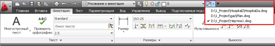
Rice. 14. Transition from one window to another.
4) Docking to the right or left of frequently used palettes. Let's make it easier to access the Properties palette.
Go to the "View" tab, click on the "Properties" button - the "Properties" palette will open. Click on the button highlighted in blue and select "Dock Left". See Fig. 15.

Rice. 15. Fixing the palette.
The Properties bar appears on the left. If you place the mouse pointer over this strip, the Properties palette appears. Moving the mouse pointer aside will hide the palette from the screen. The strip can be converted to a button. To do this, right-click on this strip and select "Icons only". See Fig. 16.

Rice. 16. Palette in the form of an icon.
At the top left, an icon will appear when you hover over which the Properties palette will appear. If you want the palette to temporarily not disappear from the screen, click on the button highlighted in red. See Fig. 17.

Rice. 17. Fixing the palette.
The palette will now be permanently on the screen. To make the palette disappear again, click on the minimize button. See Fig. eighteen.

Rice. 18. Minimize the palette.
Similarly, you can organize quick access to other palettes.
5) It happens that some of the toolbars, on any tab, collapse and they are not convenient to use. See Fig. 19. In order for them to expand, you can turn off the panels that you do not use.

Rice. 19. Disable toolbars.
To do this, place the mouse pointer on the ribbon and click the right mouse button. Next, go to "Show Panels" and uncheck those toolbars that we want to hide (in the same way, you can disable unused tabs). If the panels are still minimized, you can temporarily drag any panel into the drawing window. To do this, place the mouse cursor on the desired panel, press the left mouse button and without releasing it, drag the panel into the drawing window and release it there. Once you no longer need the panel, you can return it to the tape. We click on the button "Return the panel to the ribbon". See Fig. twenty.

Rice. 20. Return the panel to the tape.
6) Organization of quick access to the project folder. Click on the "Open" button. The "Select File" window will appear. Find the folder you would like to have quick access to (in my case, this is the "My Project" folder). We place the mouse cursor on the folder, hold down the left mouse button and, without releasing it, drag it to the "List of storages" and release it only there. See Fig. 21.

Rice. 21. Adding a folder to the list of storages.
A link to your folder will appear in the list of storages. By clicking on which you will find yourself inside the "My Project" folder. After the work with the project is finished, the link from the "List of storages" can be removed. To do this, place the mouse pointer on the desired link, press the right mouse button and select delete. See Fig. 22.

Rice. 22. Removing a folder from the list of storages.
A message will appear in which we press OK. See Fig. 23. ( The project itself will remain in the place where it lies in its integrity and safety. Only the link to it will be deleted).

Rice. 23. Communication.
7) If you have learned the commands well and rarely use the "Context Menu". You can use the right mouse button instead of the key
This will allow you to:
- End cyclic operations by pressing the right mouse button (instead of pressing
). - Call up the last completed commands with the right mouse button without looking for them on the ribbon.
Click on the "Application button" and in the window that opens, click on the "Options" button. See Fig. 5.

Rice. 5. Application button
The "Settings" window will open. In it, select the "Custom" tab and click on the "Right Mouse Button". The Right Mouse Button Configuration window appears. See Fig. 24.

Rice. 24. Setting the right mouse button
In this window, click on the circles highlighted in red and click on the "Accept" and "OK" buttons.
Now press the right mouse button - instead of the context menu, the "Settings" window will appear (since this is the last completed command). Just close it.
This is just a small part of how we can change AutoCAD settings.
How to create your own tabs on the ribbon. How to create your own toolbars, see the lesson: "Creating a Button for a LISP Program"
I sincerely hope that the information presented above will be useful to anyone.
Write in the comments:
What workspace mode do you work in?
What interface changes discussed in this lesson were useful to you?
If you are using something else that helps you in your work, then share your secrets.
If you want to receive news from my site. Subscribe.
In this tutorial we Let's start examining the workspace of the AutoCAD program. This material is related to lessons.
A workspace is understood as a set and organization of menu (ribbon) tabs and toolbars; the style and appearance of the model space; position and view of the command line; setting the status bar, etc. In general, roughly speaking, all that we see when starting the program is the AutoCAD interface.
To speak the same language, I will give you a few terms on the topic "Workspace in AutoCAD":

7 - Status bar (enable / disable drawing modes in the program).
When starting the program for the first time (starting with versions of AutoCAD 2009) by default Autocad workspace is "Draw and Annotate"(in the picture above). The menu is presented in the form of a ribbon with thematic tabs, which contain toolbars, grouped by functional belonging. This AutoCAD workspace is focused on working with 2D drawings and project documentation.
The program also provides several more pre-installed workspaces:
1. 3D basic.
2. 3D modeling.
3. Classic AutoCAD.
So let's get started!
1. Setting up and changing workspaces AutoCAD.
The workspace change button is located in the status bar in the lower right corner of the program window. To change the AutoCAD workspace, left-click (further Paintwork ) and we have a list of proposed operations .
At first, the ability to switch to a different AutoCAD workspace by clicking Paintwork by its name.
Secondly, using the option " workspace options " we call the dialog box of the same name,
![]()
in which we can configure the display of certain workspaces in the list of workspaces spaces(to do this, simply put or uncheck the boxes opposite the names of the Autocad workspaces); using buttons up down we can change the order of the spaces in the list; the separator button creates cutoffs m / d by the names of the workspaces. For the settings to take effect, press - ok.
Thirdly, consider the option " adaptation"... This option is used for global settings of the user interface, including AutoCAD workspaces. We can talk about adaptation for a very long time, so we will consider only a few settings related to today's topic.
So, after clicking on the adaptation item, the Customize User Interface dialog box, in which we see a list of workspaces.

AutoCAD is a computer-aided design system developed by Autodesk, is a CAD system and includes 2D 3D modeling tools. This lesson is devoted to the study of the program interface and is based on the latest version of AutoCAD 2014.
When creating a new working document, the program will ask you to choose an interface design template. It should be borne in mind that AutoCad in one working file is able to contain both flat and volumetric figures, as well as whole groups of separate 3D elements, which gives it a certain advantage in relation to other 2D and 3D modeling programs. In this lesson, we will focus on the default appearance in AutoCAD - acadiso. The program interface consists of:

1.
2.
3.
4.
5.
6. Working area
1. Quick Access Toolbar
![]() By default, it includes a standard set of the most commonly used commands: New, Open, Save, Print, Undo, and Redo. Does the program provide the ability to independently set commands and tools displayed on the quick access panel?
By default, it includes a standard set of the most commonly used commands: New, Open, Save, Print, Undo, and Redo. Does the program provide the ability to independently set commands and tools displayed on the quick access panel?
2. Ribbon
The structure of the ribbon consists of tabs, each containing several panels, which in turn include tools and controls. By default, the ribbon is located at the top of the window. AutoCAD allows the user to independently edit the appearance of the ribbon, as well as to make the panels floating, detaching them from the ribbon. The main elements of the Ribbon 
- Tab - Includes grouped panels. The order of the tabs on the ribbon can be changed.
- Panel - Contains a set of tools.
- Expand button - Expands the panel to display additional tools.
- Expanded panel.
- Pin - disabled by default, in this mode the expanded panel automatically collapses when you move the cursor away from it. When the pin is on, the expanded panel does not collapse.
- Panel name.
3. Status bar
The status bar includes icons for quick access and control of drawing tools. Using the context menu, opened by right-clicking on the line field, you can switch the type of display of the line - characters or text labels.
| Model - Displays model space on the drawing screen. | |
| Sheets Quick View - View and switch between sheets in a drawing. | |
| Drawings Quick View - View and switch between open drawings and sheets. | |
| Annotation Scale - The current scale of the annotation displayed. The viewport scale is linked to the annotation scale. | |
| Annotation Visibility - the mode of displaying annotative objects. | |
| Autoscale - updates the display of an annotative object when the scale is changed. | |
| Workspaces - switch workspaces and adapt their settings. | |
| Display Lock - Locks the current position of toolbars and windows. | |
| Navigation wheel - move and rotate the view in space. Includes cursor menu. | |
| Palm - with the LMB held down, it allows the mouse to move the viewport in the plane. | |
| Zoom-in and out of the view, includes several types of zoom, selectable in the submenu. | |
| Orbit - rotation of the viewport around an axis, includes several types of rotation selected in the submenu. | |
| Animation start |
? Below is a description of the main status bar tools On the left side of the line there are icons for managing and accessing drawing tools: "Anchor", "Grid", "Lineweight", "Dynamic Input".


