85. In this chapter, all directions for placing signals on the right or left side are given in the direction of travel.
86. The head of the train when moving on single-track and on the correct railway track on double-track sections is indicated by: in the daytime - with one transparent white light of a searchlight; at night it is additionally indicated by two transparent white lanterns near the bumper bar (Fig. 188).
The head of the train when moving along the wrong track is indicated by: day and night - by the red light of the lantern on the left side, on the right side - by the transparent white light of the lantern (Fig. 189).

On a locomotive following in the head of a train or without carriages, a motor-carriage train, when moving on public railway tracks on single-track and on a correct and incorrect railway track on double-track sections, a transparent white signal light of a searchlight must be turned on day and night. The head of a motor-carriage train at night can also be indicated by one transparent white light from a searchlight.
87. The head of a freight train when moving by carriages forward on single-track and along the correct railway track on double-track sections is not indicated by signals during the day, at night it is indicated by a transparent white light from a lantern near the buffer bar (Fig. 190).

When carriages move forward on the wrong track, the head of a freight train is indicated by: in the daytime - an unfurled red flag, shown on the left side by an employee accompanying the train, who is at the front transition platform; at night - with the transparent white light of a lantern near the buffer beam and the red light of a hand lantern, shown from the left side by an employee accompanying the train (Fig. 191).
88. The tail of the train when moving on single-track and on the correct and wrong railway track on double-track sections is indicated by:
1) cargo and cargo-passenger day and night - a red disc with a reflector at the buffer bar on the right side (Fig. 192);
2) passenger and postal luggage day and night - three red lights (Fig. 193).


Rice. 192 Fig. 193
A locomotive at the tail of a freight train, as well as a locomotive following without wagons, are indicated at the back: day and night - by a red light from a lantern near the buffer bar on the right side (Fig. 194).

The procedure for signaling trains when moving cars forward and not accompanied by the compiler, while ensuring the safety of train traffic and the safety of employees of railway transport organizations, is established by the owner of non-public railway tracks.
On non-public railway tracks, specialized trains (turntables) circulating in opencast mines when moving on single-track, double-track and multi-track sections when moving forward with a locomotive and cars forward are designated:
1) train head:
in the daytime - the locomotive is not indicated by signals, and the car is indicated by a red disc near the buffer bar of the car on the right side (Fig. 195);
at night - two transparent white lights of lanterns near the locomotive bumper bar (Fig. 188) or one transparent white light near the bumper rail of the car on the right side, while the head car is supplemented with a sound signaling device;

Rice. Fig. 195 Fig. 196
2) the tail of the train:
in the daytime - a red disc near the buffer bar of the car on the right side (Fig. 196), the locomotive in the tail of the train is not indicated by signals;
at night - with one transparent white light of a lantern on the buffer bar of the car on the right side (Fig. 197) or two red lights on the buffer bar of the locomotive (Fig. 198).


Rice. 197 Fig. 198
89. A push locomotive and special self-propelled railway rolling stock are signaled in the same way as a locomotive without wagons.
A push locomotive and a utility train returning from a double-track haul on the wrong track back to the railway station of departure are indicated by signals to follow the wrong track.
90. In the event of a rupture on the stretch of a freight train, the tail of the part of the train sent to the railway station shall be indicated: in the daytime - by an unfurled yellow flag at the buffer bar on the right side; at night - with the yellow light of a lantern (Fig. 199).
The last retracted part of the train is marked in the same way as the tail of a freight train.

91. Trains on multi-track sections are designated in the same way as on single-track and double-track, depending on the established order of movement on one or the other railway track of a multi-track section.
92. A snowplow when driving on single-track and on the correct railway track on double-track sections is indicated by:
1) if you have a snowplow in your head:
during the day - two yellow unfolded flags on the side hooks;
at night - two yellow lights of the side lamps, and in the direction of the locomotive - two transparent white control lights (Fig. 200);

2) if there is a locomotive in the head:
in the afternoon - two yellow flags unfolded at the buffer lamps;
at night - two yellow lights of buffer lamps (Fig. 201).
The tail of the snowplow is designated as the tail of the single following locomotive.
93. Snowblowers, when driving them in the head on the wrong railway track on double-track sections, are indicated:
in the afternoon - two yellow unfurled flags and a red unfurled flag under the yellow one on the left on the side hooks;
at night - respectively, two yellow and one red lights of the lanterns, and in the direction of the locomotive - three transparent white control lights (Figure 202).
If there is a locomotive in the head, then it is designated in the same way as a snowplow when moving in the head (Fig. 202).


94. A locomotive during shunting movements, including when moving to and from the train, at night must have one transparent white light in front and behind on the buffer beams from the side of the main control panel of the locomotive.
95. Trolleys of a removable type, track wagons and other removable mobile units, while on the stretch, must have:
on single-track and when driving on the wrong track on double-track sections: in the daytime - a rectangular shield painted red on both sides, or an unfurled red flag on a pole; at night - in front and behind the red light of a lantern mounted on a pole;
on double-track sections when following the correct railway track: in the daytime - a rectangular shield painted on the front side in white and on the back in red; at night there is a transparent white light in front and a red light of a lantern mounted on a pole behind.
Removable repair towers on electrified areas when working on the stretch must have:
on single-track and when driving on the wrong track on double-track sections: in the daytime - an unfolded red flag on both sides; at night - in front and behind the red light of the lantern;
on double-track sections when following the correct railway track: in the daytime - an unfurled red flag on the right side in the direction of trains; at night - a transparent white light of a lantern in front, and a red light of a lantern in the back.
In all cases, the signals must be fixed at the upper level of the earthed belt of the removable repair tower.
Removable repair towers and track wagons on the stretch must, in addition, be fenced on both sides with portable or hand-held red signals, carried simultaneously with the movement of the repair tower and the wagon, at a distance B specified in column 4 of Table 1, depending on the direction of the descent and the maximum permissible speed of movement on the stretch.
When working at a train station:
a removable repair tower should have: in the daytime - a red flag unfurled on both sides; at night - in front and behind the red light of the lantern;
track carriage: during the day - a board painted red on both sides, or a red flag on a pole; at night - in front and behind the red light of a lantern, fixed on a pole.
When moving along station railway tracks and turnouts, a removable repair tower and a track wagon, in addition, must be fenced on public railway tracks at a distance of at least 50 m, and on non-public railway tracks - at least 15 m on both sides by portable or hand-held red signals carried simultaneously with the movement of the removable repair tower and the track wagon.
Fencing on both sides of track bogies of various types and other removable mobile units used during work is carried out in cases established by the owner of the infrastructure, the owner of non-public railways.
If an oncoming train will follow on a double-track or multi-track section on an adjacent railway track, then the red signal protecting the removable repair tower, track car or other removable mobile unit from the front side is removed before the train passes.
On double-track electrified sections, except for sections equipped with two-way auto-blocking, and sections where passenger trains operate at a speed of more than 120 km / h, it is allowed to fence removable repair towers only from the side of train movement along the correct railway track.
The procedure for organizing the work of removable repair towers on such sections, which ensures the safety of train traffic, is established taking into account local conditions by the owner of the infrastructure, the owner of non-public railways.
Employees of railway transport divisions guarding removable repair towers, track cars and other removable mobile units, as well as workers directing the movement of removable units, should be equipped, in addition to portable shields, hand flags and signal lights, firecrackers and blowholes to signal approach trains, as well as signals to stop the train, if required.
Barrage
ZOM-80LED> 10cd, 30-235V AC / DC, IP65.
TU 3461-001-69016606-2010
Appointment of the device:
Obstruction lights (signal lamps) ZOM-80LED> 10cd TU 3461-001-69016606-2010, designed to indicate high-rise objects (obstacles) that pose a danger to the movement of air transport (crane installations, high-rise buildings and houses, chimneys, relay masts, airfields ), light marking of extended objects and for constant illumination on ground objects as a signal light.
Specifications:
This device is designed specifically for the difficult climatic conditions of the republics of the former USSR, has successfully passed climatic tests and is designed to operate at low power quality. The device is equipped with a built-in state control system, with the ability to send a signal to an external monitoring device or transmitting device, as well as a specialized power supply controller, which provides:
- Overvoltage protection;
- Protection against supply voltage fluctuations;
- Lightning protection;
- Short circuit protection in one of the clusters, which increases the "survivability" of the module.
The characteristics of the device with a red color, constant glow fully comply with the ICAO (international standards) requirements for low-intensity type A obstruction lights installed on stationary objects.
- Climatic modification: UHL1 in accordance with GOST 15150;
- Service conditions group M3 in accordance with GOST 17516.1;
- Protection degree: IP65 in accordance with GOST 14254;
- The fires are resistant to: frost, rain, salt fog, dynamic action of dust, vibration loads, solar radiation, sudden temperature changes (thermal shock);
- Light filter: transparent, red;
- Body material: polycarbonate;
- Weight: no more than 1.2 kg;
Electrical characteristics: Input supply voltage of any polarity, Uin .: 30-235V, AC / DC. Input current of any polarity, Iin. (mA): 140 ... 45; Constant current through the LED Ib., Not less (mA): 20; Maximum power consumption, no more (W): 6; Maximum switched voltage by "Kontr" contacts, (V): 350; Maximum switched current by "Kontr" contacts, (mA): 90. Lighting characteristics: The light source is a semiconductor LED device. Number of LEDs: 80pcs 12 cd each, angle 40 °; Average lifespan of an LED device: 80,000 hours. Radiation: omnidirectional, color-red; Scattering angle: standardized value 10 °, actual 30 °; Luminous intensity in the + 10 ° direction: normalized value 10 cd, actual 10 cd; Luminous intensity in the direction of -6 °: the value is not standardized, the actual value is 13.5 cd; Average luminous intensity in directions -50 ° + 50 °: the value is not standardized, the actual value is 10.4 cd
Luminous intensity in the + 6 ° direction: normalized value 10 cd, actual 13 cd;
Design advantages:
-
The condition monitoring system contains galvanically isolated, normally closed contacts, which makes it easy to integrate it into any remote monitoring structure.
The wide range of supply voltage allows switching the ZOM-80LED obstruction lights with both AC and DC power sources with a voltage of 30-235V, while polarity is not required.
The built-in condition monitoring system allows you to remotely monitor the performance of both the entire complex of obstruction lights and each individual lamp.
None of the LED light sources on the market of the Russian Federation used in obstruction lights has the entire list of advantages implemented in the ZOM-80LED
Completeness:
Basic requirements for installation and operation:
ZOM luminaires are mounted with a holder (rod) on the roofs of buildings, poles, masts, etc. When changing the lamp, turn the upper part of the fire away from its base and make sure that the gasket is installed in place during assembly. Wipe the light filter as soon as it becomes dirty with clean cotton wool, soft flannel or chamois leather without the use of solvents or abrasive substances. After cleaning, the shade should be wiped with cotton wool soaked in alcohol.
Package:
Packing of obstruction lights in accordance with GOST 23216 for storage conditions 2 (c) GOST 15150. ZOM lamps are packed in shipping containers that ensure their safety and protection from mechanical damage and precipitation.
Safety precautions:
To ensure safety during operation of the ZOM obstruction light, it is prohibited to:
- Replace the lamp with a light source with a lower luminous intensity;
- Perform any work with the ZOM obstruction lights when the voltage is on;
Assembly and operation of the obstruction light with damaged insulation.
When installing and operating the ZOM obstruction light, it is necessary to be guided by the rules for electrical installations (PUE).
Manufacturer's warranty:
The plant guarantees trouble-free operation of the product, subject to the rules of operation for 1 year!
10cd, 30-235V AC / DC, IP54 "src =" http://zom-sdzo.ru/images/banner-a1-4.jpg "width =" 690 "hspace =" 0 "height =" 687 "border = "0">
Russia. Obstruction lights, signal lamps ZOM, ZOM-SD, ZOM-48LED, ZOM-80LED, ZOM-PPM and SDZO. LLC AEROSIGNAL, Moscow, RF, is a leading manufacturer of obstruction lights, signal lamps ZOM, ZOM-SD, ZOM-48LED and ZOM-80LED and offers its customers ten modifications of signal lamps. It supplies obstruction lights, signal lamps ZOM, ZOM-SD, ZOM-48LED and ZOM-80LED to any point in the Russian Federation and the CIS. The obstruction light, a signal light ZOM with a 60 W lamp, is the best price offer on the Russian market in this segment.
Order of the Federal Air Navigation Service of November 28, 2007 N 119
"On Approval of the Federal Aviation Rules for Courts"
The "shading" zone from extended obstacles located within the inner horizontal and conical surfaces is a 100 m wide strip along the perimeter of the obstacle. The "shading" surface passes over the top of the obstacle with a downward slope of 15% (Fig. 1).
The "shadow" from obstacles located near the boundaries of the approach surface, transition surfaces or take-off surfaces does not apply to the zones of these surfaces (Fig. 1).
The height of the "shading" surface at a distance L from the "shading" obstacle is
H = Hp - 0.15L, where Hp is the height of the "shading" obstacle; L is the distance from the "shading" obstacle.
Distance L is determined according to the plan of the inner horizontal and conical surfaces.

3. Approach surface
Point obstacles located within the approach surface cannot be considered "obstructions".
To draw a zone of "shadowing" from extended obstacles on the approach surface plan (Fig. 2), lines are drawn from the edges of the "shadowing" obstacle parallel to the lateral boundaries of the approach surface.
The "shading" surface is formed by two planes, one of which passes over the top of the "shading" obstacle with a downward slope of 15% towards the runway, the other - horizontally away from the runway (Fig. 2). The "shading" surface extends either to the point of intersection with the approach surface or to the point at which the lines drawn from the edges of the "shading" obstacle (the lines forming the "shaded" zone) intersect, whichever is closer to " shading "obstacle (Fig. 2).
The height of the "shading" surface towards the runway is:
H = Hp - 0.15L.
The height of the "shading" surface in the direction from the runway is:

4. Takeoff surface
Within the take-off surface, the "shading" zone is created by any fixed obstacle (point or extended, but not light and brittle) exceeding the inclined surface of 1.6% or 1.2%, as appropriate, established by the Airfield Serviceability Standards.
Its inner boundary starts from a line drawn through the top of the "shading" obstacle perpendicular to the axis of the take-off surface zone. The "shading" surface is formed by a plane drawn horizontally from the inner edge of the area from the runway to the intersection with the take-off surface, which has a slope of 1.6% or 1.2%, as appropriate (Figure 3).
The height of the "shading" surface is equal to: Н = Нп.

g) In addition to the values indicated, the lights must be of sufficient intensity to be visible at elevation angles between + 0 deg and 50 deg.
h) Peak intensity should be achieved at a vertical angle of approximately 2.5 degrees.
i) Peak intensity should be achieved at a vertical angle of approximately 17 degrees.
fpm - flashes per minute; N / A - Not Applicable.
Appendix N 6
To
"Placement of marks and devices
on buildings, structures, communication lines, lines
power transmission, radio equipment
and other objects installed for the purpose
flight safety
vessels "approved by the order of Rosaeronavigatsia
dated November 28, 2007 N 119


Appendix N 7
to the Federal Aviation Regulations
"Placement of marks and devices
on buildings, structures, communication lines, lines
power transmission, radio equipment
and other objects installed for the purpose
flight safety
vessels "approved by the order of Rosaeronavigatsia
dated November 28, 2007 N 119
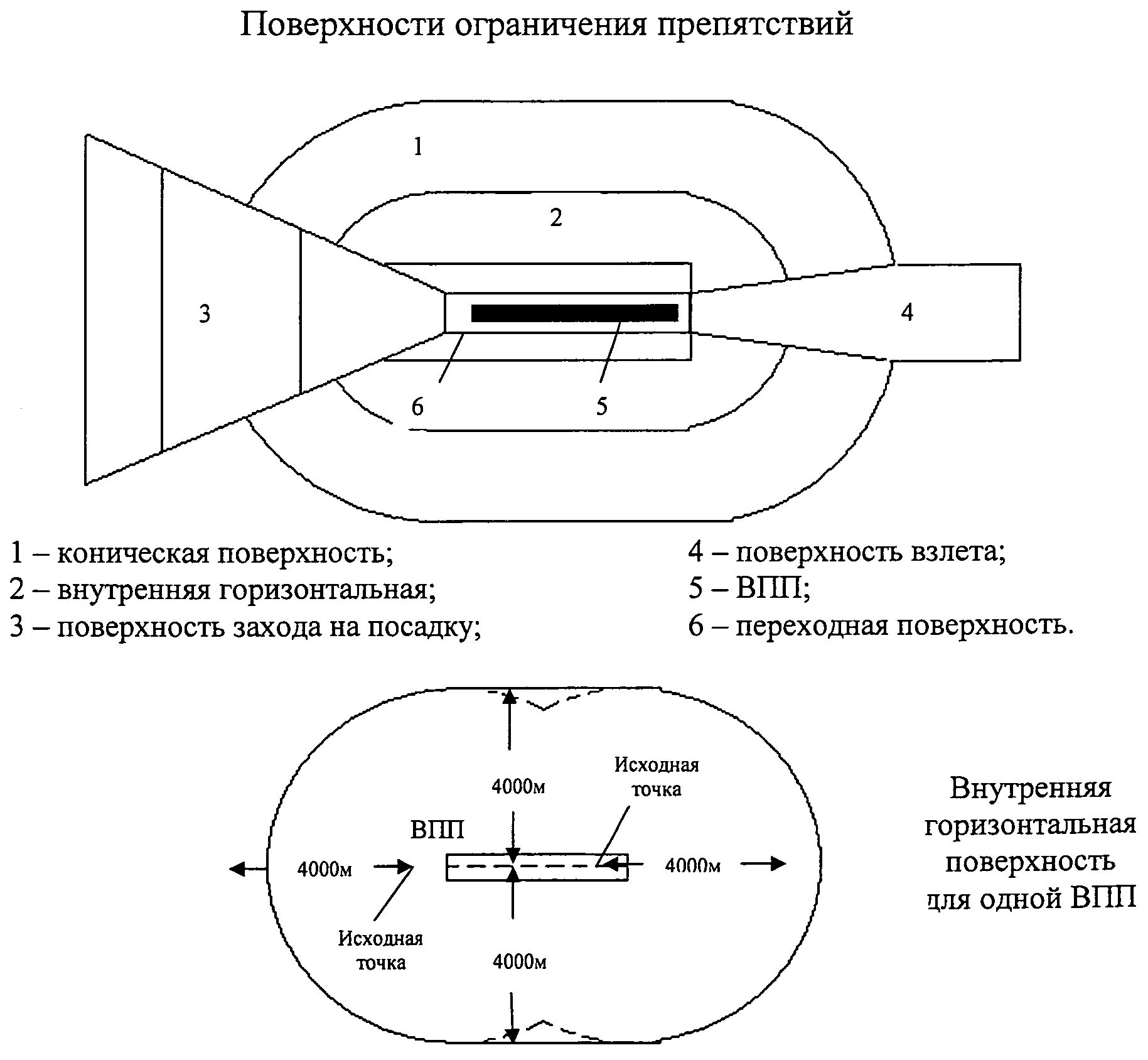
Obstacle limitation surfaces parameters
|
Surface and its parameters |
Runway direction for instrument approach |
Runway direction for approach to minima of categories I, II, III |
|
|
Runway class |
Runway class |
||
|
Conical: |
|||
|
height, m (relative to the inner horizontal surface) |
|||
|
Internal horizontal: |
|||
|
radius (R), m |
|||
|
height, m (relative to the height of the aerodrome) |
|||
|
Approach: |
|||
|
lower border length, m |
|||
|
distance from the runway threshold, m |
|||
|
discrepancy in each direction,% |
|||
|
first sector: length, m Horizontal sector, length |
|||
|
Transient: slope,% |
|||
|
Internal transition: slope,% |
Runway class |
||
|
Lower border length, m |
|||
|
Discrepancy in each direction,% |
|||
|
Appendix N 8 to the Federal Aviation Regulations "Placement of marks and devices on buildings, structures, communication lines, lines power transmission, radio equipment and other objects installed for the purpose flight safety vessels "approved by the order of Rosaeronavigatsia dated November 28, 2007 N 119  | |||
Any aircraft is equipped with on-board aeronautical and side lights, flashing (pulse) lights. This equipment helps to prevent collisions between aircraft, especially near airports, through brightly flashing light flashes. Aircraft side lights are installed in accordance with the requirements of international rules and regulations.
Functions of the external lighting equipment of the aircraft:
steering track and runway lighting;
lighting of air intakes and leading edges of the wing;
lighting of the emblem on the tail unit;
providing light indication of the aircraft in the air;
long distance warning light to prevent collision.
On passenger aircraft, they try to place the flashlights in such a way that there is no strong reflection of flashes of light on the wings, which causes the passengers to believe that there is a fire.
To illuminate the runway during landing and takeoff, two retractable headlights are installed in front of the fuselage, illuminating the turn from the runway.
Two headlights located on the fuselage are responsible for lighting the air intakes and leading edges of the wing. The emblem is illuminated by two headlights on the stabilizer.
Aeronautical white tail lights shall be located on the trailing edges of the right and left planes. The navigation lights operate in the standard mode of the right and left consoles in flight. On the ground, in the extended position, the lights are automatically switched to a lower power.
In the airfield position of the aircraft, the lights work as parking lights.
In the lower and upper parts of the fuselage, beacons are located, which have a stepwise adjustment of the intensity of light and colorless filters.
Layout of lights on airliners
Navigation lights
On the leading edge of the wingtip of the right console - green; on the leading edge of the left tip - green; white - the rear extreme point of the rudder. They work in a continuous mode.

Strobes
Located on the left wing, at the bottom of the wingtip, color - white. They work in the following mode: 50 ms on, 500 ms off.
Rotating beacon
Located on top of the keel. Operating mode: 70 ms on, 300 ms off.
Taxi lantern
Located on the nose of the fuselage, it illuminates the lower space in front of the aircraft, similar to a low-beam car light, in a narrow directional white.
Landing lights
Located in the region of a third of the span of the wing consoles. The power and range of illumination are the same as the high beam of a car. Headlights aimed at one point in white.
They are used to determine the position of the aircraft in space. The lights located on the wingtips: left - red, right - green, rear - white.
Rotating beacons and strobe lights help to visually identify the type of aircraft by the location and color of the lights. For example, in Tu-134, red flashes are located approximately in the center of the fuselage in the upper and lower parts, on Tu-154 - in the rear of the fuselage and on the keel. On the Yak-40, red flashing beacons are located on the back of the keel and on the lower part of the fuselage.

Landing lights
There are no specific requirements for the number and location of landing lights. They can be installed in the nose cone or issued on the A-pillar.
The power of the "Flash" lamp for most aircraft is 1000 watts. The principle of operation is similar to that of a photographic flash. The location differs from aircraft to aircraft.
Thus, strict requirements by international regulatory organizations are set only for airborne navigation lights, landing lights are allowed to be installed at the discretion of the aircraft manufacturer.
Requirements for aircraft on-board aeronautical lights
Colour
Lights to prevent aircraft collisions in the air must be white or red.
Front navigation lights
The color of the aeronautical front lights is red or green. They are located at the front of the aircraft parallel to each other so that the aircraft is in its normal flight position. Green light - indicator of the right side of the aircraft, red - the left.
Tail (rear) aeronautical light
It has a white color and is installed at the extreme point of the wing or at the rear tip of the tail unit.
Parking lights
For amphibious aircraft and seaplanes, the parking lights should:
- ensure the visibility of a white light for at least 2 miles in the dark;
- create a circular glow of fire when the aircraft is drifting on the water or moored in a bay.
Suspended outdoor lights are permitted.
Anti-collision lighting system
General Provisions
For night operation of an aircraft, certification requires the installation of a collision avoidance fire system that must:
- Consist of lights of an approved type, positioned in such a way that the emitted light does not interfere with the work of the crew and does not diminish their visibility.
- Meet international requirements.
Coverage area
The system must operate with sufficient lights to cover the most critical areas around the aircraft, taking into account its flight performance and configuration. The vertical angle of action of the lights must be 75 ° above the horizontal plane of the aircraft. Shading of lights by structural elements is allowed at an angle of up to 0.5 steradians.
Flashing characteristics
The rotation speed, width of the light beam, the number of color sources and other characteristics of the system are required to provide a flash frequency of 40 to 100 flashes per minute. In areas where the light source is blocked, the frequency of flashes may be exceeded up to 180 flashes per minute.
Light barriers for high-rise buildings, which are an obstacle to the movement of aircraft, are carried out in accordance with the "Manual on Aerodrome Service in Civil Aviation" (NAS GA-86) in order to ensure the safety of flights at night and in poor visibility (low cloudiness, fog, precipitation).
Obstacles are subdivided into aerodrome and linear obstacles. Aerodrome obstacles are located on the territory near the aerodrome, i.e. on the terrain adjacent to the aerodrome, over which aircraft maneuvering takes place in the airspace. For airfield obstacles, a light barrier is provided for any height.
Linear obstacles include high-rise structures located outside the aerodrome territory, within airways or on the ground. The height of the linear obstacles at which a skylight is required depends on the location of the obstacles. (This provision does not apply to obstacles with a height of more than 100 m, which must be provided with a light bar in all cases.)
If linear obstacles are located on the territory of air approach strips (VFR), where there is a climb after takeoff and descent during an approach, then a light barrier is arranged for obstacles: any height - with a departure strip (OP) distance of up to 1 km; with a height of more than 10 m - at a distance from the OP from 1 to 4 km; with a height of 50 m and more - at a distance from the OP from 4 km to the end of the TIR.
Light barriers, regardless of height, must have the following linear obstacles:
Obstacle restrictions that rise above established surfaces;
Objects of departments of internal affairs, radio navigation and landing.
Since electrical designers do not have information about how obstacles are located relative to airfields, airways, airway strips, air strips, the need for light barriers of certain objects and their assignment to airfield or linear obstacles should be determined by the tasks of the general designer, drawn up on the basis of the requirements of the regional departments of the Ministry of Civil Aviation and the Ministry of Defense.
In the construction part of the project of high-rise structures, access to light barriers(stairs, platforms with fencing, etc.).
Obstacles must have light barriers at the very top (point) and below every 45 m... As a rule, the distances between intermediate tiers should be the same. It must be borne in mind that the height of any obstacle should be considered its height relative to the absolute elevation of the terrain section on which it is located. In the case when the structure stands on a separate hill, which stands out from the general flat relief, the height of the obstacle is considered from the foot of the hill.
For linear obstacles located inside built-up industrial areas, a light barrier is installed from the top point to a height of 45 m above the average building height.
Long obstacles (Fig. 1) or a group of them, located close to one another, must have a light barrier at the top points along a common outer contour with an interval of not more than 45 m. The highest obstacles included in the above contour receive an additional light barrier. For extended obstacles in the form of horizontal networks (overhead power lines (OHL), antennas, etc.) suspended between the masts, the light fence is arranged on the masts (supports) regardless of the distance between them.
At the upper points of obstacles, and for extended obstacles also in the upper corner points, two lights (main and backup) are installed, working simultaneously or one at a time if there is a device for automatically turning on the backup fire when the main one fails. If in any direction the light of the light barrier is obscured by another (near) object, then an additional light must be provided on this object. In this case, the fire covered by the object, if it does not indicate an obstacle, is not installed.
Rice. 1. An example of the placement of the lights of the light barriers of an extended high-rise obstacle: A - no more than 45 m; B - 45 m and more... Rice. 2. An example of the placement of light barriers along the general contour of a group of high-rise structures: A - no more than 45 m; B - 45 m and more

Rice. 3. Example light barriers on the chimney: H - no more than 45 m; A, B, C - network phases
On chimneys, overhead lights are placed 1.5-3 m below the pipe edge. The number and location of obstruction lights on each tier of a chimney or mast must be such that at least two obstruction lights are visible from any direction of flight. Examples of the placement of obstruction lights on some obstacles are shown in Fig. 2 and 3.
As light barriers, either ZOL-2M with an SGA220-130 incandescent lamp (with a 1F-S34-1 base), as well as ESP-90-1 type lights are used.
In view of the absence of explosion-proof obstruction lights, prior to the development of such lighting devices, light barriers in hazardous areas can be made with lamps of type N4BN-150) with a 100 W LN, with a red paint coating on the inner surface of the protective glass of the luminaire.
Obstruction lights installed with glass upwards at a height of approximately 1.5 m from the level of the service platform. ZOL-2M and N4BN-150 devices are installed on a stand made of a steel pipe with a nominal bore of 20 mm, attached to building structures (site fencing, building parapet, etc.). ZOL-2 devices are mounted using a bracket included in the device kit.
The light barrier of an obstacle is related to the degree of ensuring the reliability of power supply to power consumers of category I and is powered from two independent sources by two lines (Fig. 4), starting from switchgears that are constantly energized (switchboards of substations, outdoor lighting cabinets of an enterprise, lead-in cabinets of workshops that operate obstacles)
In the absence of two independent sources, it is allowed to supply the obstruction lights with two lines from one source, provided that its operation is as reliable as possible. One line is allowed to power the light barriers of several obstacles, provided that protection devices are installed on the branches to each of them.

Rice. 4. An example of a power supply circuit for the lights of a light fence on a chimney: 1 - a box with single-pole automatic switches; 2 - power cabinet with one three-pole automatic switch and a magnetic starter; A, B, C - network phases
Power supply of light barriers of supports can be carried out by capacitive power take-off from overhead lines.
The obstacle light barriers are generally recommended to be switched on and off automatically depending on the level of natural light using photo switches. In addition to automatic control, centralized remote control must be provided from the control room for outdoor lighting of the enterprise or from the workshop to which the high-rise obstacle belongs.
Usually, automatic and centralized remote control of light barriers it is recommended to combine it with the control of outdoor lighting for the whole enterprise or for its individual sections.
The closest protection devices are recommended to be provided with single-pole (installed mainly on the lower part of a high-rise structure). Control and protection equipment for light barrier lines should be inaccessible to random persons (use of cabinets with lockable doors, installation of cabinets in electrical rooms, etc.).
Remote control circuits for light barriers should ensure their automatic re-inclusion after power is restored (push-button control is not allowed). To power the light barrier, as a rule, it is allowed to lay (in the ground and along the structure) unarmoured plastic-insulated cables with aluminum conductors.
Examples of some control schemes for light barriers are shown in Fig. 5 and 6. In the diagram in Fig. 5, automatic and centralized remote control of light barriers of high-rise buildings and lighting of the territory of the enterprise, where these structures are located, are combined.
The cabinets of the first AQ1 and second AQ2 light barriers are usually controlled from one AK control cabinet. If the enterprise has two control cabinets for power cabinets AQ1 and AQ2, it is recommended to control them from different AK cabinets. The AK cabinet is located in the control room for outdoor lighting of the enterprise.
Cabinets AQ1 and AQ2 installed in the workshop (of which the skylight of a high-rise building is a part) provide the ability to control the light enclosure directly from the workshop. Local control of light barriers during repair work is carried out from box 1 (Fig. 4), installed on the basis of a high-rise structure.
The diagram in Fig. 6 is taken from a typical project chimney light barriers... It provides common control circuits for the obstruction lights powered by the first and second sources, which increases the likelihood of simultaneous failure of all obstacle obstruction lights.

Rice. 5. Example of a circuit control of light barriers... Option one: QF1-QF3 - circuit breaker; F1-F3 - fuse; KM1-KM5 - magnetic starter; A1 A2 - automatic photo switch; BF1, BF2 - photoresistance; SA1-SA3 - control selector (key); ZF1 - box with single-pole automatic switches; HL1-HL4 - signal light fittings; SA4-SA5 - switch; AQ1, AQ2 - power cabinet for light barriers from the first and second sources; AK - control cabinet; M - local government; О - disabled; D - remote control; A - automatic control; 1,2 - inputs from the main and reserve power supplies of control circuits; 3 - to the AQ2 cabinet of the second power supply, the circuit is similar to that of the AQ1 cabinet of the first power supply; 4 - to power cabinets for light barriers of other objects; 5 - to control circuits of outdoor lighting lines; 6 - to the lights of the light barriers.

Rice. 6. An example of a control scheme for a light barrier. Option two: QF1, QF2 - automatic switch; KM1, KM2 - magnetic starter; KV1, KV2 - phase failure relay (together with the HL1 and HL2 lamps, they provide a signal about the failure of inputs 1 and 2); KV3, KV4 - intermediate relay; A1 - automatic photo switch; BF - photoresistance; F1, F2 - fuse; SA - selector (key) control; HL1-HL4 - signal light fittings; AQ1, AQ2 - power cabinet light barriers from the first and second sources; AK - control cabinet; О - disabled; M - local government; A - automatic control; D - remote control; 1,2- inputs from the first and second power sources of the light barriers; 3, 4 - to the lights of the light barriers.
Note. The scheme provides for the possibility of remote control from the control room for the company's outdoor lighting. In this case, free block contacts of magnetic starters KM1, KM2 are used for signaling.
The scheme is designed for individual power supply and control of each obstacle (chimney), which is impractical in the conditions of large enterprises with a large number of high-rise buildings. Power cabinets AQ1 and AQ2 are located in the workshop, of which the chimney is a part. The AK control cabinet, depending on the general outdoor lighting control scheme, is located either in the outdoor lighting control center, or in the same place where the AQ1 and AQ2 light barriers power cabinets.


