LED is a semiconductor device with nonlinear current-voltage characteristic(VAH). Its stable operation, first of all, depends on the magnitude of the current flowing through it. Any, even minor, overload leads to degradation of the LED chip and a decrease in its working life.
To limit the current flowing through the LED to the right level, electrical circuit must be supplemented with a stabilizer. The simplest current-limiting element is a resistor.
Important! The resistor limits but does not stabilize the current.
Calculating a resistor for an LED is not a difficult task and is done in a simple manner. school formula. But with physical processes flowing in the p-n junction of the LED, it is recommended to get to know each other better.
Theory
Mathematical calculation
Below is the basic electrical diagram in the very simple version. In it, the LED and resistor form a series circuit through which the same current (I) flows. The circuit is powered by an EMF voltage source (U). In operating mode, a voltage drop occurs across the circuit elements: across the resistor (U R) and across the LED (U LED). Using Kirchhoff's second rule, we obtain the following equality:  or its interpretation
In the above formulas, R is the resistance of the calculated resistor (Ohm), R LED is the differential resistance of the LED (Ohm), U is the voltage (V).
The R LED value changes as operating conditions change semiconductor device. IN in this case the variable quantities are current and voltage, the ratio of which determines the value of resistance. A clear explanation of this is the current-voltage characteristic of the LED.  On initial section characteristics (up to approximately 2 volts), the current gradually increases, as a result of which the R LED has great importance. Then the pn junction opens, which is accompanied by sharp increase current with a slight increase in applied voltage.
By simply transforming the first two formulas, you can determine the resistance of the current-limiting resistor: U LED is the nameplate value for each individual type of LED.
Graphic calculation
Having the current-voltage characteristic of the LED under study in hand, you can calculate the resistor graphically. Of course, this method is not widely used practical application. After all, knowing the load current, you can easily calculate the value of the forward voltage from the graph. To do this, it is enough to draw a straight line from the ordinate axis (I) until it intersects with the curve, and then lower the line to the abscissa axis (U LED). As a result, all the data for calculating the resistance have been obtained.
However, the graph option is unique and deserves some attention.
Let's calculate a resistor for an LED with a rated current of 20 mA, which must be connected to a 5 V power source. To do this, draw a straight line from the 20 mA point until it intersects with the LED curve. Next, through point 5 V and a point on the graph, draw a line until it intersects with the ordinate axis and get maximum value current (I max), approximately equal to 50 mA. Using Ohm's law, we calculate the resistance: In order for the circuit to be safe and reliable, it is necessary to prevent overheating of the resistor. To do this, find its dissipation power using the formula:
In what cases is it possible to connect an LED through a resistor?
You can connect an LED through a resistor if the issue of circuit efficiency is not paramount. For example, using an LED as an indicator to illuminate a switch or mains voltage indicator in electrical appliances. In such devices, brightness is not important, and power consumption does not exceed 0.1 W. When connecting an LED with a consumption of more than 1 W, you need to be sure that the power supply produces a stabilized voltage.
If the input voltage of the circuit is not stabilized, then all noise and surges will be transmitted to the load, disrupting the operation of the LED. A striking example serves as a car electrical network, in which the voltage on the battery is only theoretically 12 V. In the simplest case, do LED backlight in the car it follows through a linear stabilizer from the LM78XX series. And in order to somehow increase the efficiency of the circuit, you need to turn on 3 LEDs in series. Also, a power supply circuit through a resistor is in demand for laboratory purposes for testing new LED models. In other cases, it is recommended to use a current stabilizer (driver). Especially when the cost of the emitting diode is comparable to the cost of the driver. You receive a ready-made device with known parameters, which just needs to be connected correctly.
Examples of calculations of resistor resistance and power
To help beginners get their bearings, here are a couple of practical examples of calculating resistance for LEDs.
Cree XM-L T6
 In the first case, we will calculate the resistor required to connect a powerful LED to a voltage source of 5 V. Cree XM–L with bin T6 has the following parameters: typical U LED = 2.9 V and maximum U LED = 3.5 V at current I LED =0.7 A. The typical value of U LED should be substituted into the calculations, since. it most often corresponds to reality. The calculated resistor value is present in the E24 row and has a tolerance of 5%. However, in practice it is often necessary to round the results to the nearest value from the standard series. It turns out that, taking into account rounding and a tolerance of 5%, the real resistance changes and, following it, the current changes in inverse proportion. Therefore, in order not to exceed the operating load current, it is necessary to round the calculated resistance upward.
Using the most common resistors from the E24 series, it is not always possible to select the desired value. There are two ways to solve this problem. The first involves the sequential inclusion of an additional current-limiting resistance, which should compensate for the missing Ohms. Its selection must be accompanied by control current measurements.
The second method provides higher accuracy, as it involves installing a precision resistor. This is an element whose resistance does not depend on temperature and other external factors and has a deviation of no more than 1% (series E96). In any case, it is better to leave the actual current slightly less than the nominal value. This will not greatly affect the brightness, but will provide the crystal with a gentle operating mode.
The power dissipated by the resistor will be:
The calculated resistor power for the LED must be increased by 20–30%.
Let's calculate the efficiency of the assembled lamp:
Example with LED SMD 5050
 By analogy with the first example, we will figure out what resistor is needed for. Here you need to take into account the design features of the LED, which consists of three independent crystals.
If the LED SMD 5050 is single-color, then the forward voltage in the open state on each crystal will differ by no more than 0.1 V. This means that the LED can be powered from one resistor, combining 3 anodes into one group, and three cathodes into another. Let's select a resistor for connecting a white SMD 5050 with the following parameters: typical U LED = 3.3 V at a current of one chip I LED = 0.02 A. The closest standard value is 30 Ohms. ![]()
We accept for installation a limiting resistor with a power of 0.25 W and a resistance of 30 Ohms ±5%.
The SMD 5050 RGB LED has a different forward voltage for each die. Therefore, you will have to control the red, green and blue colors with three resistors of different values.
Online calculator
The online calculator for LEDs presented below is a convenient addition that will perform all the calculations independently. With its help, you don't have to draw or calculate anything manually. All you need is to enter the two main parameters of the LED, indicate their number and the voltage of the power source. With one click of the mouse, the program will independently calculate the resistance of the resistor, select its value from the standard range and indicate the color marking. In addition, the program will already offer ready-made diagram inclusions.
The LED has very little internal resistance; if it is connected directly to the power supply, the current will be high enough to burn it out. Copper or gold threads that connect the crystal to external outputs, can withstand small surges, but if they are greatly exceeded, they burn out and power stops flowing to the crystal. Online calculation resistor for LED is made based on its nominal work force current.

- 1. Online calculator
- 2. Basic parameters
- 3. Features of cheap LEDs
Online calculator

Draw up a connection diagram in advance to avoid errors in calculations. The online calculator will show you the exact resistance in Ohms. As a rule, it will turn out that resistors with this value are not produced, and you will be shown the nearest standard value. If you cannot make an accurate selection of resistance, then use a larger value. A suitable value can be made by connecting the resistance in parallel or in series. Calculation of resistance for an LED can be avoided if you use a powerful variable or trim resistor. The most common type is 3296 at 0.5W. When using a 12V power supply, up to 3 LEDs can be connected in series.

Resistors come in different accuracy classes, 10%, 5%, 1%. That is, their resistance can have an error within these limits of positive or negative side.
Do not forget to take into account the power of the current-limiting resistor, this is its ability to dissipate a certain amount of heat. If it is small, it will overheat and fail, thereby breaking the electrical circuit.
To determine the polarity, you can apply a small voltage or use the diode test function on a multimeter. Different from resistance measurement mode, usually supplied from 2V to 3V.
Main settings

Also, when calculating LEDs, you should take into account the spread of parameters; for cheap ones they will be maximum, for expensive ones they will be more the same. To test this setting, you must enable them in equal conditions, that is, sequentially. By reducing the current or voltage, reduce the brightness to slightly glowing points. Visually, you will be able to estimate that some will glow brighter, others dimly. The more evenly they burn, the less spread. The LED resistor calculator assumes that the characteristics of the LED chips are ideal, that is, the difference is zero.

The drop voltage for common low-power models up to 10W can be from 2V to 12V. As power increases, the number of crystals in a COB diode increases; each has a drop. The crystals are connected in chains in series, then they are combined into parallel circuits. At powers from 10W to 100W the reduction increases from 12V to 36V.
This parameter must be specified in the technical LED characteristics chip and depends on the purpose:
- colors blue, red, green, yellow;
- three-color RGB;
- four-color RGBW;
- two-tone, warm and cool white.
Features of cheap LEDs

Before choosing a resistor for the LED on online calculator, you should make sure the parameters of the diodes. The Chinese sell a lot of LEDs on Aliexpress, passing them off as branded ones. The most popular models are SMD3014, SMD 3528, SMD2835, SMD 5050, SMD5630, SMD5730. All the bad stuff is usually made under the Epistar brand.

For example, most often the Chinese cheat on SMD5630 and SMD5730. The numbers in the markings only indicate the case size of 5.6mm by 3.0mm. In branded ones, such a large case is used to install powerful 0.5W crystals, so buyers of SMD5630 diodes directly associate it with 0.5W power. The cunning Chinese takes advantage of this and installs a cheap and weak crystal in the 5630 case with an average power of 0.1W, while indicating the energy consumption of 0.5W.
 Chinese LED bulbs corn
A clear example there will be car lamps and LED corn in which supplied a large number of weak and low-quality LED chips. The average buyer believes that the more LEDs, the better the light and the higher the power.
 Automotive lamps at the weakest ice 0.1W
To save money, my LED colleagues are looking for decent LEDs on Aliexpress. Looking for good seller, which promises certain parameters, they order and wait a month for delivery. After tests, it turns out that the Chinese seller cheated and sold junk. You'll be lucky if the seventh time you get decent diodes and not junk. Usually they make 5 orders, and without achieving results, they go to place an order in a domestic store that can make an exchange.
An ordinary small LED looks like a plastic lens cone on conductive legs, inside which there is a cathode and an anode. In the diagram, the LED is depicted as a regular diode, from which the arrows show the light emitted. So the LED serves to produce light when electrons move from the cathode to the anode - visible light is emitted.
The invention of the LED dates back to the distant 1970s, when incandescent lamps were used to produce all the light. But today, at the beginning of the 21st century, LEDs have finally taken the place of the most efficient sources of electric light.
Where is the “plus” of the LED and where is the “minus”?
To properly connect an LED to a power source, you must first observe the polarity. The anode of the LED is connected to the plus “+” of the power source, and the cathode is connected to the minus “-”. The cathode connected to the minus has a short lead, the anode, accordingly, has a long lead - the long leg of the LED - to the plus “+” of the power source.
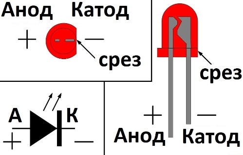
Take a look inside the LED: the large electrode is the cathode, its is the minus, the small electrode, which just looks like the end of a leg, is the plus. And next to the cathode, the LED lens has a flat cut.
Do not hold the soldering iron on the leg for a long time
Soldering the leads of the LED should be done carefully and quickly, because the semiconductor junction is very afraid of excess heat, so you need short movements of the soldering iron, touch its tip to the soldered leg, and immediately move the soldering iron to the side. It is better to hold the soldered LED leg with tweezers during the soldering process to ensure that heat is removed from the leg, just in case.
A resistor is required when testing an LED

We come to the most important thing - how to connect an LED to a power source. If you want, then you should not directly connect it to the battery or power supply. If your power supply is 12 volts, then use a 1 kOhm resistor in series with the LED being tested for backup.
Do not forget about polarity - the long lead is positive, the lead from the large internal electrode is negative. If you do not use a resistor, the LED will quickly burn out; if you accidentally exceed the rated voltage, a large current will flow through the p-n junction, and the LED will almost immediately fail.
There are LEDs different colors, however, the color of the glow is not always determined by the color of the LED lens. White, red, blue, orange, green or yellow - the lens can be transparent, but when you turn it on, it turns out to be red or blue. Blue and white LEDs are the most expensive. In general, the color of the LED glow is influenced primarily by the composition of the semiconductor, and as a secondary factor by the color of the lens.

Finding the resistor value for the LED
The resistor is connected in series with the LED. The function of the resistor is to limit the current, make it close to the nominal value of the LED, so that the LED does not instantly burn out, and operates in normal nominal mode. We take into account the following initial data:
Vps - power supply voltage;
Vdf - forward voltage drop across the LED in normal mode;
If - rated current of the LED in normal lighting mode.
Now, before finding , we note that the current in the series circuit will be constant, the same in each element: the current If through the LED will be equal to current Ir through a limiting resistor.
Therefore Ir = If. But Ir = Ur/R - according to Ohm's law. A Ur = Vps-Vdf. Thus, R = Ur/Ir = (Vps-Vdf)/If.
That is, knowing the voltage of the power supply, the voltage drop across the LED and its rated current, you can easily select a suitable limiting resistor.
If the found resistance value cannot be selected from the standard range of resistor values, then take a resistor of a slightly larger value, for example, instead of the found 460 Ohms, take 470 Ohms, which are always easy to find. The brightness of the LED will decrease very slightly.

Example of resistor selection:
Let's say there is a 12 volt power supply and an LED that needs 1.5 volts and 10 mA to glow normally. Let's select a quenching resistor. The resistor should drop 12-1.5 = 10.5 volts, and the current in the series circuit (power supply, resistor, LED) should be 10 mA, therefore from Ohm’s Law: R = U/I = 10.5/0.010 = 1050 Ohm. Select 1.1 kOhm.
What power should the resistor be? If R = 1100 Ohm, and the current is 0.01 A, then, according to the Joule-Lenz law, the resistor will emit thermal energy Q = I*I*R = 0.11 J, which is equivalent to 0.11 W. A resistor with a power of 0.125 W will do, there will even be some reserve.
Series connection of LEDs
If your goal is to connect several LEDs into a single light source, then it is best to make the connection in series. This is necessary so that each LED does not have its own resistor to avoid unnecessary energy losses. LEDs of the same type, from the same batch, are most suitable for serial connection.
Let's say you need to connect 8 LEDs of 1.4 volts each with a current of 0.02 A in series to connect to a 12 volt power source. Obviously, the total current will be 0.02 A, but the total voltage will be 11.2 volts, so 0.8 volts at 0.02 A current must be dissipated in the resistor. R = U/I = 0.8/0.02 = 40 Ohm. We select a 43 ohm resistor of minimum power.
Parallel connection of LED chains is not the best option

If you have a choice, it is best to connect LEDs in series rather than in parallel. If you connect several LEDs in parallel through one common resistor, then due to the variation in the parameters of the LEDs, each of them will not be on an equal footing with the others, some will glow brighter, accepting more current, and some, on the contrary, will be dimmer. As a result, one of the LEDs will burn out earlier due to rapid degradation of the crystal. Better for parallel connection LEDs, if there is no alternative, apply a different limiting resistor to each chain.


