In lamps and flashlights, two circuits are used - serial and parallel connection of LEDs. These schemes have a lot of variations and combined options, each of them has its own advantages and disadvantages.
To understand which connection diagram is better, you need to find out what the current-voltage characteristic is and what it is like for an LED.
The photo shows an LED matrix for connecting to a 220V network
Basic theoretical issues
Current-voltage characteristic (abbr. VAC) is a graph displaying the dependence of the amount of current flowing through any device on the voltage applied to it. A simple and very capacious characteristic for the analysis of nonlinear components. With its help, you can select operating modes and determine the characteristics of the power source for the device.
Take a look at an example of linear and nonlinear I-V curves.
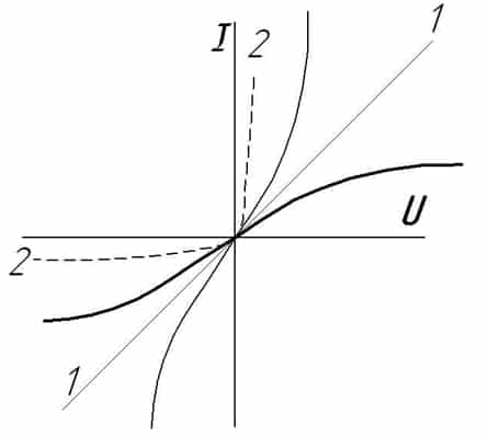
Graph number 1 in the figure displays the linear dependence of current on voltage, which is what all resistive devices have, for example:
- Incandescent lamp;
- heater;
- resistor (resistance);
Graph number 2 is the current-voltage characteristic characteristic of p-n junctions diodes, transistors and diodes.
Learn more about how diodes work
Which LED connection should I choose: series or parallel? This greatly depends on the operating conditions and the power source, as well as the voltage and current stabilization system. For the right choice both options need to be considered.
Initially, we were talking about the current-voltage characteristic for a reason; let’s consider in detail its form for LED devices.

Please note that in the voltage range lower than 2.5V, very little or no current flows through the LED. Having overcome the level of 2.5 volts, current begins to flow through the diode and it lights up in the area from 2.5 to 3 volts. After this level, the current begins to increase rapidly.
For 5 mm white light diodes, the operating current is 20 mA at 3V, and at 3.5 volts the current will be 80 mA, which is four times higher than the nominal value.
The brightness of the diode, although it depends on the current flowing through it, is too large values The LED does not glow much brighter than at nominal. Therefore, you should not experiment with high indicators - your diodes will simply burn out.
Voltage values may vary depending on the types and design of LEDs; this is influenced by their number in one package, color, and even the material that was chosen as the basis of the chip.
How to connect correctly?
When connecting LEDs in parallel, you need to use a limiting resistor for each diode, as shown in the figure below. This makes it possible to set the current for each of the elements of the electrical circuit.
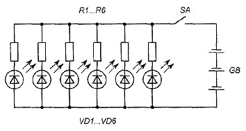 Scheme parallel connection LEDs
 Below is the diagram NOT correct connection resistor in the circuit.
 This is not the right way to connect
 When connecting LEDs and any other consumers in parallel, the voltage at their terminals will be equal. On the one hand, this is good, but not for diodes. Each LED, even a set taken from the same batch, has a small technological variation in parameters. The voltage required to achieve the rated current may vary slightly within tenths of a volt.
You saw above current-voltage characteristic device and you can easily conclude that a slight excess of the rated voltage leads to an avalanche-like increase in current and overheating. Some suggest excluding the resistor from this circuit; this connection of LEDs is the worst!
The total current in the circuit is equal to the sum of the currents in each of the branches of the parallel circuit. If you choose how to connect LEDs to operate in a circuit with high voltage (6 or more volts), it is better to use a series connection.
Series connection of diodes
With this circuit, you can use diodes in circuits with any voltage.
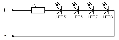
The voltages between the elements will be distributed in the right quantity, and you set the current with a resistor. Parallel connection LEDs do not allow you to achieve this result. When connected in series, the total current in the circuit will be equal to current through one of the elements.
Online calculator for calculating a resistor
| Connection type: | |
| Supply voltage: | Volt |
| LED forward voltage: | Volt |
| Current through LED: | Milliamp |
| Number of LEDs: | PC. |
| Results: | |
| Exact resistor value: | Ohm |
| Standard resistor value: | Ohm |
| Minimum resistor power: | Watt |
| Total power consumption: | Watt |
Connection options
To make a serial connection of 220V LEDs, use the diagram below.
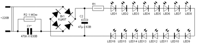
IN in this case V to a greater extent capacitor C1 limits the current; it plays the role of reactance. We wrote more about calculating a capacitor in. To obtain the required capacitance value of the capacitor, use an online calculator.
Modern interiors are characterized by large living spaces that are divided into different living areas. Small rooms are being replaced by apartments with an open plan, characterized by kitchen, living room, bedroom, and study areas. These spaces are separated by floors, ceilings, partitions and lighting. It is with their own hands that homeowners create a cozy, warm environment that emphasizes objects, shapes, and satisfies their life needs. An important part of creating comfort zones is connecting the right lighting, since for each zone or room it has its own characteristics. Places for work, reading, cooking, and relaxation must be illuminated in accordance with their functional tasks.
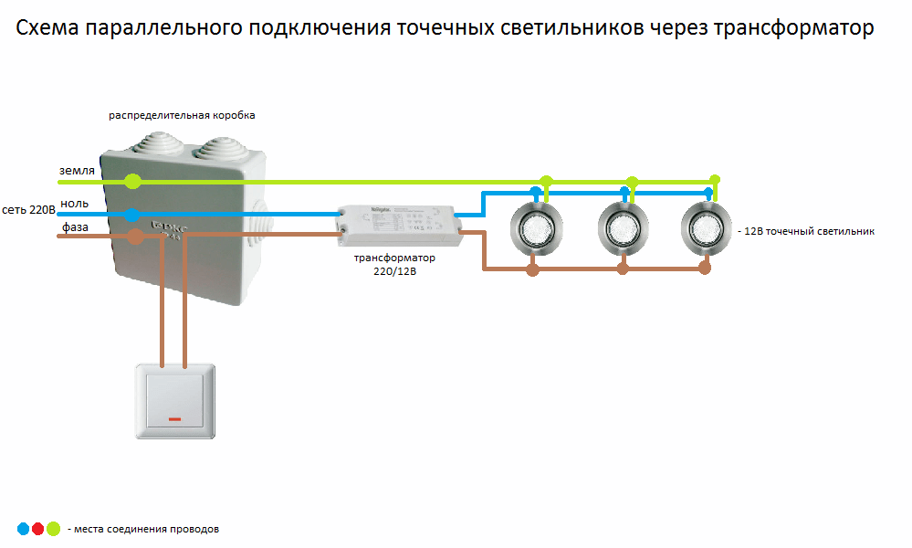
The correct connection diagram for lighting elements ensures uniform illumination of all corners of the living space of the room, highlighting and emphasizing their purpose with the help of distributed light. small in size and power successfully perform such tasks. Lighting fixtures are mounted on suspended ceilings. He will show you how to connect spotlights clearly and in detail. electrical diagram, as well as the connection algorithm. Installation of these elements is easy even with your own hands. You can find out about this in our article.
Note
It is important to remember that the location and configuration of ceiling lighting fixtures must be planned at the design stage.
Rules for connecting lamps to a 220V network
- The circuit consists of junction boxes, wires and corrugations.
- It is important to use exclusively copper wire. If there were twists in the wires, it is better to solder and insulate them.
- A separate flexible wire is allocated for each of the lamps. Connection and connection of them together occurs through copper sleeves or a special “terminal block”, which is then additionally insulated using insulating tape.
- Before installing ceilings, it is important to check the wiring and light bulbs with a switch.
Before installation on the ceiling surface, it is important to determine the location of the built-in lamps. By their design, such lighting devices cover a lighting sector of only 30º. On the other hand, due to its compactness, the scheme for their installation can be quite dense. If you follow it, then there can be quite a lot of them on different ceilings.
To ensure optimal illumination of the room, the installation diagram of light elements should be as follows:
- The distance between the points of light should be no more than a meter.
- Holes for lamps should be located at a distance of 25-30 mm from the nearest frame.
- The spotlight should be located at a distance of 60 cm from the wall.
- It is better to separate the lighting circuits of different zones with a separate switch.
You can install and connect it yourself. The technology and design are universal - the same for all types of suspended ceilings.
Technical characteristics of spot lighting
- It is important to use the same type of luminaires for certain lighting circuits.
- Powerful lighting devices over 40 watts can damage the suspended ceiling.
- For plastic ceiling options, it is recommended to choose wiring that is more fire-resistant compared to plasterboard ceilings.
- IN mandatory The wire for lighting must be stranded, soft and flexible.
- You should periodically check the fastening and tightening of the clamping bolts of the wiring fastenings.
How to connect lighting yourself
- Planning. If the suspended ceiling is formed from several levels, the connection of the lamps should be made with the allocation of separate lighting circuits, which are controlled by a separate 220-volt network switch. The installation diagram is developed in advance.
- Pulling and securing wires. It is recommended to fasten the wiring to metal profiles using special plastic ties. At the places where the light points are attached, form loops that can be easily hooked and pulled out through the holes drilled in the ceiling panels. At the same time, it is important to allow them to sag slightly.
In another option, you can stretch the wiring with your own hands from the first hole to the rest, but in this case the wiring will lie directly on the drywall itself from the inside.
- Drilling holes for spotlights. The layout takes on its final contours after installation of the ceiling surface. In the case of plastic ones, it is better to place the lighting fixtures in the center of the panels, and not at the junction. The holes are made using a drill and a special attachment called a “crown”. It's easy to drill them with your own hands. It is important to choose the correct nozzle diameter.
- Lighting connection. It is important to connect 220 V, following a strict algorithm:
- Fastening lamps. Bend the side brackets with your own hands until they stop and insert them into the hole. After this, the staples will snap into place. Insert the lamp and secure it at the top with the retaining ring. This design securely holds the lamps on the ceiling. After this, you can connect the main wire to the network.
fluorescent lamps"data-essbishovercontainer="">At the final stage, all that remains is to check the operation of the distributed light lighting. Thus, following the technology and observing the sequence of work, you can easily install built-in spotlights on a suspended ceiling with your own hands.
Fluorescent lamps are connected in accordance with a slightly more complex circuit compared to their closest “relatives” - incandescent lamps. To ignite fluorescent lamps, starting devices must be included in the circuit, the quality of which directly determines the life of the lamps.
To understand the features of circuits, you must first study the structure and mechanism of action of such devices.
Each of these devices is a sealed flask filled with a special mixture of gases. Moreover, the mixture is designed in such a way that the ionization of gases requires a much smaller amount of energy compared to ordinary incandescent lamps, which allows for significant savings on lighting.
In order for a fluorescent lamp to continuously produce light, it must maintain a glow discharge. To ensure this, the required voltage is supplied to the electrodes of the light bulb. the main problem is that a discharge can only appear when a voltage is applied that significantly exceeds the operating voltage. However, lamp manufacturers have successfully solved this problem.
Electrodes are installed on both sides of the fluorescent lamp. They accept voltage, thanks to which the discharge is maintained. Each electrode has two contacts. A current source is connected to them, which ensures heating of the space surrounding the electrodes.
Thus, the fluorescent lamp lights up after its electrodes have warmed up. To do this, they are exposed to a high-voltage pulse, and only then does the operating voltage, the value of which must be sufficient to maintain the discharge.
| Luminous flux, lm | LED lamp, W | Contact fluorescent lamp, W | Incandescent lamp, W |
|---|---|---|---|
| 50 | 1 | 4 | 20 |
| 100 | 5 | 25 | |
| 100-200 | 6/7 | 30/35 | |
| 300 | 4 | 8/9 | 40 |
| 400 | 10 | 50 | |
| 500 | 6 | 11 | 60 |
| 600 | 7/8 | 14 | 65 |
Under the influence of a discharge, the gas in the flask begins to emit ultraviolet light, which is imperceptible to the human eye. So that the light becomes visible to humans, the inner surface of the flask is coated with a phosphor. This substance shifts the frequency range of light into the visible spectrum. By changing the composition of the phosphor, the range of color temperatures also changes, thereby providing a wide range of fluorescent lamps.
Fluorescent lamps, unlike simple incandescent lamps, cannot simply be switched on electrical network. For an arc to appear, as noted, the electrodes must warm up and a pulse voltage must appear. These conditions are ensured using special ballasts. Most widespread received ballasts of electromagnetic and electronic types.
Classic connection via electromagnetic ballast
Features of the scheme
In accordance with this circuit, a choke is connected to the circuit. Also, the circuit must include a starter.
Starter for fluorescent lamps - Philips Ecoclick StartersS10 220-240V 4-65W
The latter is a low-power neon light source. The device is equipped with bimetallic contacts and is powered from an electrical network with variable current values. The throttle, starter contacts and electrode threads are connected in series.
Instead of a starter, an ordinary electric bell button can be included in the circuit. In this case, voltage will be supplied by holding the bell button pressed. The button must be released after the lamp is lit.
The operating procedure of the circuit with an electromagnetic type ballast is as follows:
- after being connected to the network, the inductor begins to accumulate electromagnetic energy;
- electricity is supplied through the starter contacts;
- the current rushes through the tungsten heating filaments of the electrodes;
- the electrodes and the starter heat up;
- the starter contacts open;
- the energy accumulated by the throttle is released;
- the voltage on the electrodes changes;
- a fluorescent lamp gives light.
In order to increase the indicator useful action and reducing interference that occurs when the lamp is turned on, the circuit is equipped with two capacitors. One of them (the smaller one) is located inside the starter. His main function is to dampen sparks and improve neon impulse.
Among key advantages circuits with electromagnetic type ballast can be distinguished:
- time-tested reliability;
- simplicity;
- affordable price.
- As practice shows, there are more disadvantages than advantages. Among them it is necessary to highlight:
- impressive weight of the lighting fixture;
- long lamp on time (on average up to 3 seconds);
- low efficiency of the system when operating in cold conditions;
- relatively high energy consumption;
- noisy throttle operation;
- flickering, which negatively affects vision.
Connection procedure
Connecting the lamp according to the considered scheme is carried out using starters. Next, we will consider an example of installing one lamp with the inclusion of a model S10 starter in the circuit. This modern device It has a non-flammable body and high-quality construction, which makes it the best in its niche.
The main tasks of the starter come down to:
- ensuring the lamp is turned on;
- breakdown of the gas gap. To do this, the circuit is broken after a fairly long heating of the lamp electrodes, which leads to emission powerful impulse and directly break through.
The throttle is used to perform the following tasks:
- limiting the current value at the moment of closing the electrodes;
- generating voltage sufficient for gas breakdown;
- maintaining the discharge combustion at a constant stable level.
In the example under consideration, a 40 W lamp is connected. In this case, the throttle must have the same power. The power of the starter used is 4-65 W.
We connect in accordance with the presented diagram. To do this we do the following.
First step
In parallel, we connect the starter to the pin side contacts at the output of the fluorescent lamp. These contacts represent the leads of the filament of the sealed bulb.
Second step
We connect the inductor to the remaining free contacts.
Third step
We connect the capacitor to the supply contacts, again, in parallel. Thanks to the capacitor, reactive power will be compensated and interference in the network will be reduced.
Connection via modern electronic ballast
Features of the scheme
Modern connection option. The circuit includes an electronic ballast - this economical and improved device provides a much longer service life of fluorescent lamps compared to the option discussed above.
In circuits with electronic ballast, fluorescent lamps operate at higher voltages (up to 133 kHz). Thanks to this, the light is smooth and flicker-free.
Modern microcircuits make it possible to assemble specialized starting devices with low power consumption and compact dimensions. This makes it possible to place the ballast directly into the lamp base, which makes it possible to produce small-sized lighting fixtures that are screwed into an ordinary socket, standard for incandescent lamps.
At the same time, the microcircuits not only provide power to the lamps, but also smoothly heat the electrodes, increasing their efficiency and increasing their service life. It is precisely these fluorescent lamps that can be used in combination with dimmers - devices designed to smoothly regulate the brightness of light bulbs. You cannot connect a dimmer to fluorescent lamps with electromagnetic ballasts.
By design, the electronic ballast is an electrical voltage converter. A miniature inverter transforms direct current into high-frequency and alternating current. It is this that goes to the electrode heaters. As the frequency increases, the heating intensity of the electrodes decreases.
The converter is switched on in such a way that first the current frequency is at high level. The fluorescent light bulb is connected to a circuit whose resonant frequency is significantly lower than the initial frequency of the converter.
Next, the frequency begins to gradually decrease, and the voltage on the lamp and the oscillating circuit increases, due to which the circuit approaches resonance. The heating intensity of the electrodes also increases. At some point, conditions are created that are sufficient to create a gas discharge, as a result of which the lamp begins to produce light. The lighting device closes the circuit, the operating mode of which changes.
When using electronic ballasts, the lamp connection diagrams are designed in such a way that the control device has the ability to adapt to the characteristics of the light bulb. For example, after a certain period of use, fluorescent lamps require more high voltage to create the initial digit. Ballast will be able to adapt to such changes and provide required quality lighting.
Thus, among the many advantages of modern electronic ballasts, the following points should be highlighted:
- high operating efficiency;
- gentle heating of the electrodes of the lighting device;
- smooth switching on of the light bulb;
- no flicker;
- possibility of use in low temperature conditions;
- independent adaptation to the characteristics of the lamp;
- high reliability;
- light weight and compact dimensions;
- increasing the service life of lighting devices.
There are only 2 disadvantages:
- complicated connection diagram;
- higher requirements for correct installation and quality of components used.
Connection procedure
All necessary connectors and wires are usually included with the electronic ballast. You can see the connection diagram in the presented image. Also, suitable diagrams are given in the instructions for ballasts and lighting fixtures themselves.
In such a scheme, the lamp is switched on in 3 main stages, namely:
- the electrodes warm up, which ensures a more gentle and smooth start and the resource of the device is preserved;
- a powerful impulse is created that is required for ignition;
- the operating voltage value is stabilized, after which voltage is supplied to the lamp.
Modern lamp connection schemes eliminate the need to use a starter. Thanks to this, the risk of ballast burnout in case of starting without a lamp installed is eliminated.
Circuit for connecting two lamps in series
The scheme for connecting two fluorescent light bulbs to one ballast deserves special attention. The devices are connected in series. To complete the work you need to prepare:
- induction throttle;
- two starters;
- directly fluorescent lamps.
Connection sequence
First step. A starter is connected to each light bulb. The connection is parallel. In the example under consideration, we connect the starter to the pin output at both ends of the lighting fixture.
Second step.
Free contacts are connected to the electrical network. In this case, the connection is made in series, through a choke.
Third step.
Capacitors are connected in parallel to the contacts of the lighting device. They will reduce the severity of interference in the electrical network and compensate for the resulting reactive power.
Important point! In ordinary household switches, this is especially typical for budget models, the contacts can stick under the influence of increased starting currents. In view of this, for use in conjunction with fluorescent lighting devices, it is recommended to use only high-quality switches specially designed for this purpose.
Video - Connection diagram for fluorescent lamps


